EXERCISE 5: Add Pumping to the Model with the Well (WEL) package and Simulate Steady State Conditions with Pumping
1. In the equivalent directory that you are working in for the class problem, create directory C:\TEMP\YOURNAME\MODFLOW\exer\ex5
2. Copy my ex5_after_tutorial.gwv file there or move yours from gwvtut
3. Open GWV
- File>Open
Browse
for C:\TEMP\YOURNAME\MODFLOW\exer\ex5
- Select ex5.gwv
- OK
- Select ex5.gwv
at the bottom of the window that appears set the working directory to your version of C:\temp\yourname\modflow\exer\ex5
-
Print as much as possible to the output file for checking purposes
- Models>MODFLOW>OutputControl
- uncheck the Disable printing box
- Models>MODFLOW>PrintFormats
- print all relevant items for your problem
- Models>MODFLOW>OutputControl
-
Model>MODFLOW>Packages
- Set the root name to exss5
- Check the Well Package
- Assign unit 12 to the well package
- OK
- Set the root name to exss5
- 6.
File>SaveAs
- ex5.gwv in C:\temp\modflow\exer\ex5
- MODFLOW page
8-3
- OR
- MODFLOW96 pages 29-30
- OR
- MODFLOW2000 pages 69-70
OR
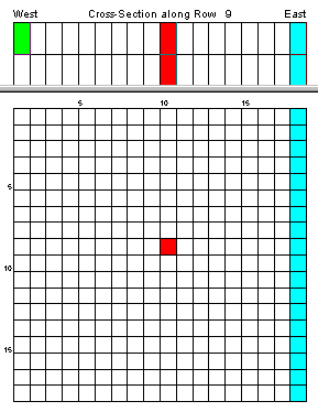
A > select the add a Well button
Click on row 9, column 10
- Adjust the coordinates to 9500,9500, the screen top and bottom to layer 1, and enter the flow rate of -1
- Repeat for layer 3
if you used this option you will see a dot on the screen representing the well - OR
- OR
- BCs>Well
- BCs>Insert>SingleCell
- Click on row 9, column 10
- Enter the flow rate of -1
- Switch to layer 3
- BCs>Insert>SingleCell
- Click on row 9, column 10
- Enter the flow rate of -1
- if you used the last option your screen would look like:

- BCs>Well
- Yes to create files
first
- Yes to view error file
- Yes to Process results
- Check the path to the output files and correct as necessary before importing them
-
This step can cause problems because sometimes you think you are not getting
the answer you expect but it is because you are looking at the wrong output
files. This is the place to check that.
- Correct the path for and Check the cell-by-cell flow files as well
- OK
- Yes to view error file
-
Find the new the wel file in your directory and view it. It should look like
this: Well File
- Peruse the MODFLOW output file, looking for conditions that you do not expect
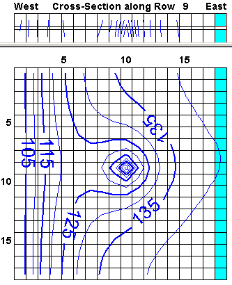
- View the heads
- Plot>Contour>Parameters(Plan)
- Choose reasonable contour information
- Your map should look like:
- (if the cross section does not look like this, set GWV to row 9 and layer 3) view other layers too

- Does this make sense? If not, communicate with me
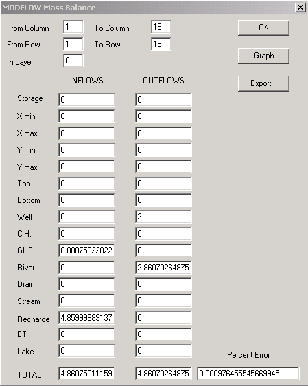
- Check the Mass Balance
- Plot>MassBalance>ModelSummary (below was run with sip, tol = 1e-5, max iter=500)

Does this make sense? If not, are some of the terms you expect to see missing? How is the mass balance? If you find problems, go to MODFLOW> Packages and check that the proper packages are included and the budget terms for each are being written to the budget file. If some of the items are missing, add them, create the files again, and rerun MODFLOW, then import the results with the flow terms checked. If you still have problems, write to me.- While you have gwv on row 9
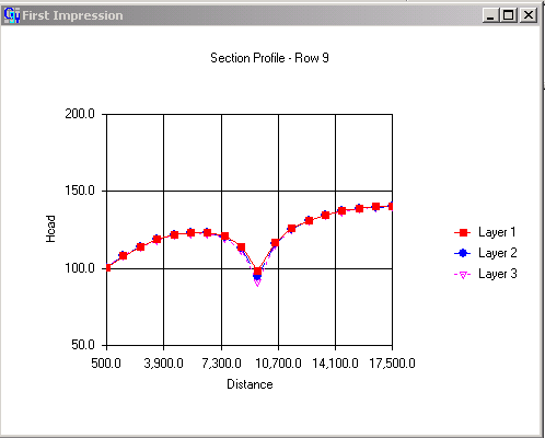
- View a cross section of the heads
- Plot>Profile>Heads
- Double Click on the Axis Labels
- Visit both the x and y axis and use reasonable variables
- Your plot should look like

- Does this make sense? If not, communicate with me
- Is flow upward or downward in the model? answer
10. Explore all aspects of this model- Does everything make sense?
- If not, write to me
- Peruse the MODFLOW output file, looking for conditions that you do not expect