EENG 383
LED matrixBinary LED display
The following image is of an 8x8 LED array.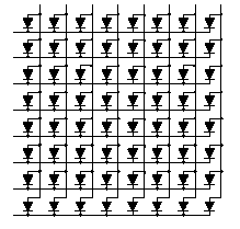
The technical documentation for these LEDs states that they can handle 10mA continous current and up to 80mA at a 10% duty cycle. You are to use the PIC18F452 and any additional circuitry needed to display a binary image on the LED array. We will call any image that consists of LEDs which are either on or off as a binary image.
Solution
So how can we display images on the display. We will do this by scanning the array one row at a time at a rate over 60Hz. From left to right, lets label the columns of the array c0 to c7. From top to bottom label the rows of the array r0 to r7. Now in order to illuminate the LEDs in row 5, you would set r5=0 and all the other row values to 1. Then in order to light up an LED in that row you would sets its corresponding column bit to 1. To turn off an LED you would set its corresponding column bit to 0.Firmware
Our algorithm will display a binary image stored in a global array called array. The rows of the LED array are aliased to a variable called r. Likewise the columns of the LED array are aliased to a variable called c. The code to set row 5 to logic 0 would look like, r[5]=0; What follows is the pseudo code to display the binary array on the LED array.while(1) {
for(row=0; row<7; row++) {
r[row]=0;
for(col=0; col<7; col++) c[col] = array[row][column];
delay(1/60 second);
r[row]=1;
} }
Hardware
In order to operate the LED array, it should first be noted that you just cannot wire-up the PIC outputs to the array. The current capabilities would not allow the LEDs to light up to their full potential. Instead you should use an amplifier. We know that a single BJT can be used as a currently amplifier. However, a pair of BJTs can use used as a super current amplifier called a darlington pair. This configuration will be shown in class to amplify the input current by a factor of beta^2. Now a single darlington pair would certainly be able to source or sink the necessary current, however in our application we need 8 of them to source current and 8 of them to sink current. Fortunately, Toshiba makes just the part. Now we can hook the current source driver to the columns of the array and the sink to the rows of the array. Well almost, we need some current limiting resistors. These can be hooked in series between the row outputs and the darlington current sinks. The resistor value should be set to pump as much current as possible through the LED.Gray Scale Display
Modify the firmware for the previous problem as follows. Create a program that can display an 8x8 gray scale image on the LED array. A gray scale image is composed of pixels which can have one of 256 different illumination levels, from full off to full on. The global array array is an 8x8 array where each entry is an 8-bit value.Firmware
A first shot at the firmware would have a counter going from 0 to 255. If the value store in an array index is less than the current count then the corresponding LED should be turned off. This cycling through the 256 illumination levels should be performed in a 60th of a second. Thus, we need to scan the entire LED array in 1/(60*256) = 1/15,360 of a second.while(1) {
for (duty=0; duty<256; duty++) {
for(row=0; row<7; row++) {
r[row]=0;
for(col=0; col<7; col++)
if (duty > array[row][column]) c[col]=0; else c[col]=1;
delay(1/15,360);
r[row]=1;
} } }
Is there any improvements to the above algorithm. It might
be nice to spread out the on and off times of an individual LED
through the duty loop. For example lets say that LED 4,4 has
its duty cycle set to 128. In our algorithm, this LED would be
on fir the first half of the DUTY for loop and off for the second
half of this loop. Wouldn;t it be nicer to have the LED turn on and
off through the entire loop. This would result in the same
illumination, but perhaps it would add a softer illumination???