EENG 383
Port ExtenderBasic Idea
When working on any project with a microcontroller, an embedded engineer need be concerned with which devices are connected to which pins. In many cases, there is not a choice, an I2C perherpial must be connected to the pins associated with the I2C subsystem. On a sufficently complex project, there may come a point where the number of I/O pins required by the perherphial devices exceed the number of I/O pins on the microcontroller. When this happens, there are a couple of choices. In some cases, it may be best to replace the microcontroller you are using with one that has more I/O. This replacement offers you the oippurtunity to reevaluate the performance (speed and I/O) of the current microcontroller and the expanding list of perhipheral devices that are being integrated with it. Replacing the microcontroller is a big deal, perhaps requiring the engineering team to change software and spin new PCBs. Not a light decision, epsecially late in a design. If you are running low on I/O ports there is another option, use a port expander.A port expander is any digital device that offers more I/O ports than it uses. The increased number of I/O ports comes at a cost, usually time and/or functionality. At a high level, there are two types of port expander, combination and sequential. Combinational port expansion typically uses decoders or multiplexers and we will not discuss them further. Sequential port expanders use some form of shift register to shift in or out the outputs or inputs. These will be our focus in the coming paragrahs.
Expanding the number of output
In order to increase the number of outputs from a microcontroller, one common chips that you can use is the 74HC164, 8-bit parallel-out serial shift register. This chip takes a clock and data line as input and shifts in values on the data line (A and B) on the positive edge of the clock CLK into a hift register. The output of the shift register is sent to the 8 output pins, QA … QH.The easiest way to interface to this chip is through the PICs SPI module. A sample configuration is shown below at right. Some of the pins are hardwired to constant voltages as shown. The HC varients of the chip should operate fine at 3.3V.
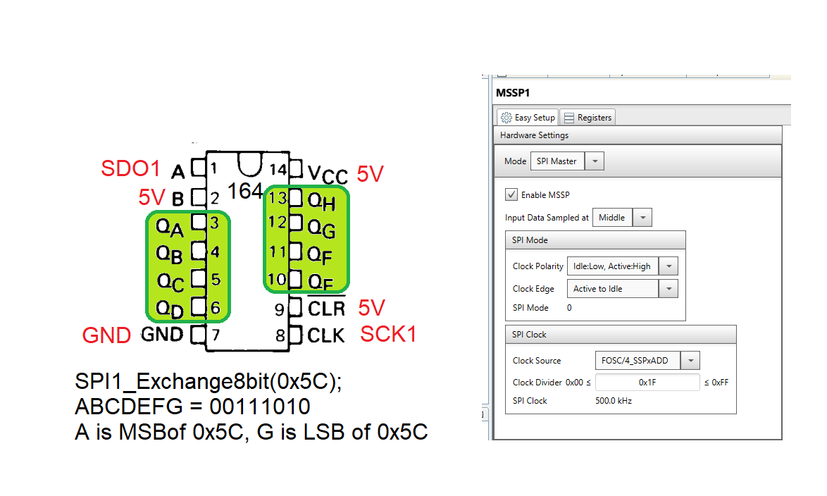
In order to accomodiate designs requiring more than 8-bits, two or more 74HC164 can be connected in series, daisy-chaining them together. This can be acomplished by sharing a common clock to all the 74HC164 chips. The QH of one 74HC164 is then connected to the A input of the next 74HC164, creating a longer shift register. As alway consult the technical documents for detailed on the function of the pins.
Expanding the number of input
The 74HC166 is a 8-bit parallel input, serial output devices. The inputs are provided through the A … H inputs. A positive logic level on the SHIFT/LOAD pin accompanied with a positive edge on CLOCK pin, causes the 74HC166 to latch the inputs into an internal shift register. Then the SPI subsystem of the PIC can be used to send a dummy piece of data to the 74HC166. The 74HC166 ignores the SDO line of the SPI and instead uses the clock pulses generated by the SCLK pin of the PIC to send out data from the QH pin to the SPI subsystem of the PIC.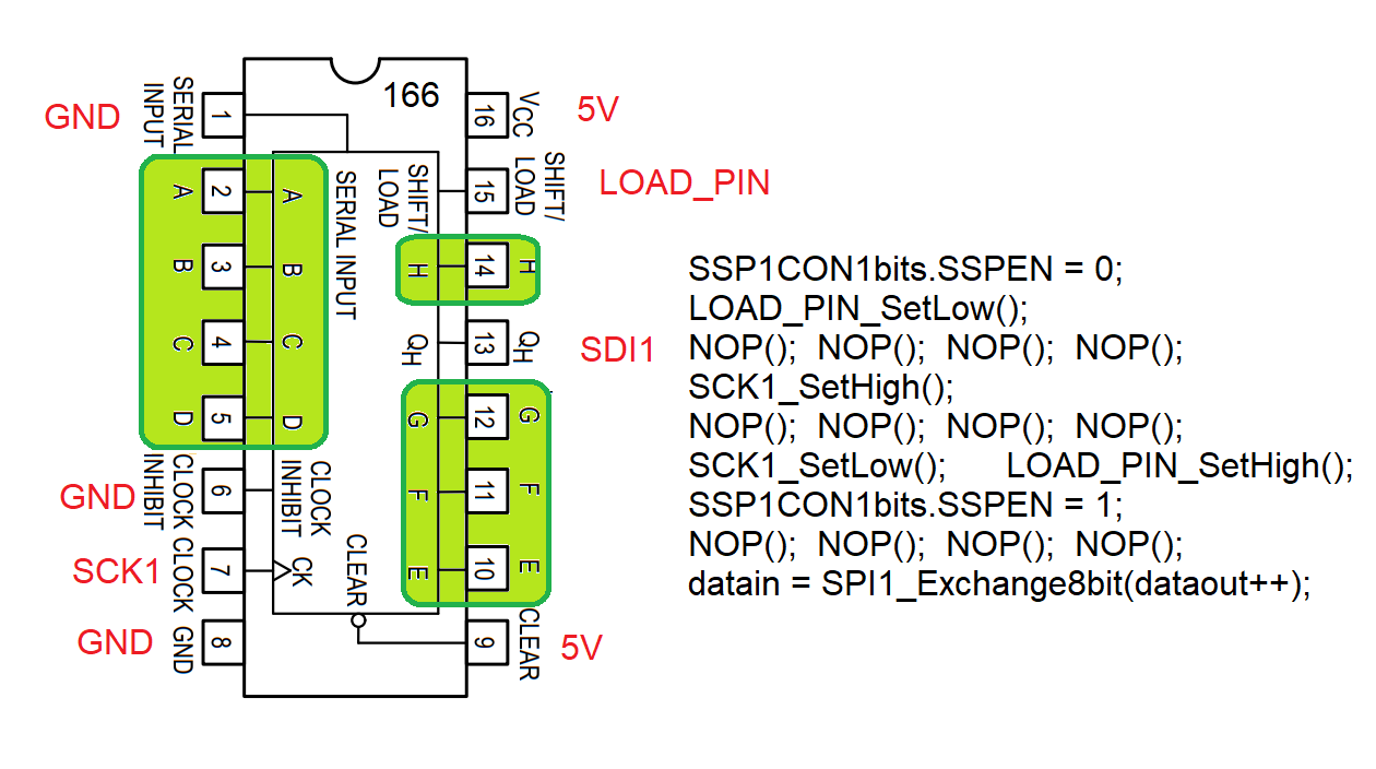
Several 74HC166 can be daisy-chained together by having all the 74HC166's share the SCK and LOAD_PIN. The QH output of one 74HC166 is attached to the SERIAL_INPUT pin of the next 74HC166 forming a longer shift register. You would need to perfom multiple SPI reads in order to read in the longer shift register. As always, consult the 74HC166 technical documents as well as the PIC techinical documents to determine the best harward connections and software calls.