EENG 383
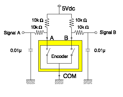
Rotary EncodersBeyond its input knob, a rotary encoder will usually have 3 pins. These three pins can be thought of as part of a simple switching system. The schematic below shows a rotary encoder in yellow and the external parts added to make it function correctly.

From this figure you can see that when a switch is open the corresponding output signals is pulled high to logic 1. The resistors and capacitors are put in this circuit at the manufactures recommendation in order to eliminate switch bouncing. When a switch is open, the corresponding output signal goes to logic 0. The correspondence between the rotation of the input know and the pattern of outputs displayed on the two signal outputs forms what is called a quadrature output.
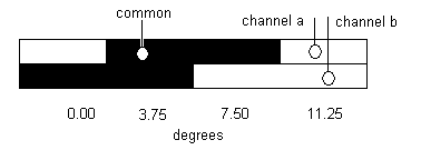
The two switches inside of a rotary encoder is built from an encoder wheel, which is a a circular plate with a funny shaped copper pattern. This copper pattern is attached to the common pin of the encoder. The two other pins are attached to copper contacts which drag against the encoder wheel. Sometimes these contacts make contact with the common pin and sometimes they don't. In the figure below a section of the encoder wheel has been removed. The shaded section of the wheel is attached to the common pin. The two other contact pins (called channel a and channel b) are shown.

In their current configuration, the contact pins are not attached to the common pin, hence output a logic 1. Imagine that the contacts both moved to the left, over the 7.5 degree mark. Then channel a would output a 1, while channel 0 would output a zero. As the contacts progressed further to the left they would sweep out the pattern shown in the table below.
| angle | channel a | channel b |
| 11.25 | 1 | 1 |
| 7.50 | 0 | 1 |
| 3.75 | 0 | 0 |
| 0.00 | 1 | 0 |
The binary pattern shown in this table should look familiar, its the order used in the arrangement of cells in a kmap. Why is this significant? Because the cells of a kmap were arranged so that adjacent cells had binary representation that differed by a single bit. This is important, because if a rotary encoders outputs changed by two bits then its entirely possible that one of the two bits would change first, possibly causing confusion about the current state of the encoders position.
Its clear that the figure above only shows a segment of the encoder wheel, but how did we arrive at the angles shown. Well, this encoder has 24 detents per revolution. This implies that there are 15 degrees between consecutive detents. Since the transition between consecutive detents takes the encoder through 4 patterns, then there are 3.75 degrees between consecutive patterns.
Now, lets get back to a statement that was made earlier, "the rotation of the input know and the pattern of outputs displayed on the two signal outputs forms what is called a quadrature output." What does it mean to say a rotary encoder has quadrature outputs. Well if you plot a timing diagram of the channel a and channel b outputs through time as the encoder know is rotated, you would see that the two channel are 90 degree out of phase with one another. This means that if we shifted one of the channels 90 degree the two channels would be congruent.
The phase of the two channels of output gives the engineer valuable information about the direction of rotation. For example in the figure above, assume that the encoder knob is hooked up to the encoder wheel and that the contacts are stationary. If the wheel was rotated in a clockwise (cw) direction then the outputs would change from 00 to 10 (outputs are listed with channel a in the msb and channel b in the lsb). Hence anytime that you see a 00 to 10 transition on the outputs you know that the know has been rotated in a clockwise direction. Similarly, if you see the encoder outputs transition from 00 to 01 then you know that the know has been rotated in a cc direction.
Firmware
The encoder is assume to be configured with all the external hardware required to make it operate correctly. Furthermore, the PIC is assume to be configured as follows. Channel a and channel b to the port b are wired up to the interrupt on change pins (RB4-RB7). The PIC is configured to generate an interrupt when one of these inputs changes. Assume that the encoder pins are aliased to A and B.Write a program which sets a global variable dir to 1 when the encoder rotates in a cw direction and -1 when rotated in a ccw direction. Main may clear the dir variable so that it be notified when the wheel is moved.
#int INT_RB
//------------------------------------
// RB_ISR
// output:  1 if rotation was cw (smaller angles)
//	   -1 if rotation was ccw (larger angles)
//	    0 if rotation was illegal
//------------------------------------
void RB_ISR() {
    static unsigned int8 oldA, oldB;

    if (oldA == 0) {
	if (oldB == 0) {
	    if (A == 0) {
		if (B == 1) dir  = -1;
		else dir = 1;
	    } else {
	.
	.
	.
} // end RB_ISR
#int INT_RB
//------------------------------------
// RB_ISR
// output:  1 if rotation was cw (smaller angles)
//	   -1 if rotation was ccw (larger angles)
//	    0 if rotation was illegal
//------------------------------------
void RB_ISR() {

    encoder[16]={0,-1,1,0,1,0,0,-1,-1,0,0,1,0,1,-1,0};
    static unsigned int8 index;

    index = (index << 2) & 0x0F;
    index = index | (A << 1);
    index = index |  B;
    dir  = encoder[index];

} // end DIR