EENG 383
Lab 6 - In-lab activitiesRequirements
Working in teams of two, read through the following lab activity and perform all the actions prescribed. You do not need to document bullet items. Make a record of your response to numbered items and turn them in a single copy as your teams solution on Canvas using the instructions posted there. Include the names of both team members at the top of your solutions. Use complete English sentences when answering questions. If the answer to a question is a table or other piece of art (like an oscilloscope trace or a figure), then include a sentence explaining the piece of art. Only include your answers, do not include the question-text unless it is absolutely needed.Objective
The objective of this lab is to familiarize you with the serial packets sent from an IR remote control unit.Note
The gesture recognition hardware present in some cell-phones will emit bursts of IR radiation, appearing as spurious IR data packets in our environment. This can be very frustrating to achieving the objectives of your and your neighbors lab. So please take a moment to put your cell phone in an enclosed space like a backpack or pocket during the duration of the lab.External Hardware
We will be working with the remote control decoder to understand the messages coming from a remote control unit and converting them into binary sequences. In order to do this you must first be familiar withRemote control decoder
To start, you you must be familiar with the operation of the Vishay Infrared Receiver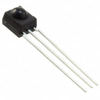
- Go to the Bill of Materials spreadsheet linked in the in-lab activities associated with Lab 01. Use the DigiKey part number for the 38kHz remote control decoder to find the part on Digikey website. What is the manufacture part number? Download the technical documents at the Datasheets link.
- Using the technical documents and the model number of our remote control decoder, what is the carrier frequency of our part?
- What wavelength of light(nm) is the remote control decoder most sensitive to? What figure did you consult to determine this answer?
- Look at the development board layout, what I/O pin on the PIC is the Vout pin from the IR decoder connected to?
IR LED
In order to communicate to an remote control decoder like the one we have on our development board, we need a LED that transmits photons at the wavelength corresponding to the maximum relative spectral sensitivity given in the remote control decoders technical documents. In the Bill of Materials used in the previous question, find the Digikey part number for the "IR LED" and get the technical documents.- What is the peak emitted wavelength of this LED? Hint, you can find this in the graph showing "Relative Spectral Emission".
- What is the Relative Radiant Intensity of light emitted by the LED when viewed 10° off center? Note, both sides of the Radiation Characteristics graph show the same information, they just present it in different ways.
- We will be running this IR LED at 10% duty cycle at 38kHz at room
temperature. Use this information to determine the following values
in the "Permissible Pulse Handling Capability" graph:
- T (state your answer in µs)
- tp (state your answer in (µs)
- D (state your answer as a decimal, NOT as a percentage)
- IF (provide a bound, like "greater than", on the answer because our value is off the graph).
Internal Subsystem
In order to build an IR communication system our PIC microcontroller will need to control the IR LED using a PWM waveform that turns on and off at 38kHz. The data sent out by the IR LED will be received by the IR decoder module that will convert it into a sequence of 0 and 1's. These bits will be sent to EUSART2 which will convert these bits into bytes. Let's look a little closer at each of these subsystems to better understand their capabilities and how they will be configured in our program.PWM
Today's code uses a CCP subsystem in PWM mode to pulse the IR LED at 38kHz. The CCP subsystem uses TMR2 to establish the period of the PWM waveform. Your code will change the duty cycle of the PWM waveform using a MCC call.
- Look at the schematic of the development board posted on the class home page. What pin of the PIC drives the network of electrical components associated with the LED labeled "INFRARED"? What CCP CCP subsystem is associated with this pin?
- Complete the following table by computing the maximum period of
TMR2 with the given prescaler. Remember that "maximum period" means
the amount of time TMR2 would need to count from 0 all the way back
to 0. You may want to consult Chapter 13 of the PIC18(L)F2X/4XK22
Data Sheet if you have questions about how TMR2 operates.
TMR2 Prescaler Maximum Period 1:1 1:4 1:16 - Compute the period of a 38kHz waveform. What is the smallest TMR2 prescaler that has a maximum period greater than 38kHz?
- Look through the inLab06 code (linked below) and identify the MCC function which sets the duty cycle of the CCP subsystem associated with the IR LED.
Let's start our examination of the EUSART2 subsystem by first looking at the schematic of the development board to answer the following question.
- What pin of the PIC is the IR decoder (called "GP1UQ70QS") connected to?
- Open up the PIC18(L)F2X/4XK22 Data Sheet and go to page 6 (you may have a handout of this page from an in-class handout) and list the pins of the PIC associated with EUSART2 and their names (find this in the EUSART column).
In order to read the bits coming in from the IR decoder you must tell the PIC EUSART2 subsystem how long each bit is. The Baud rate is the number of bits per second sent/received. For example, a Baud rate of 1200 means that 1200 bits per second are sent/received. In this case, each bit takes 1/1200 of a second or 833 µs. Since today's program both sends and receives bits at the same Baud rate, we will need to know how to configure the EUSART2 subsystem to change Baud rate and will need to know how many 1:1 prescaled TMR1 counts correspond to each of these Baud rates. In order to set the Baud rate of the EUSART2 subsystem, the EUSART2 module divides down the main oscillator, Fosc by a value contained in the Baud Rate Generator (BRG). In order to switch between Baud rates, as you will do in this assignment, you will need to update the values in the SPBRGH2:SPBRG2 register pair.
-
The Baud rate of EUSART2 is given by the following formula:
			    Fosc
	Baud rate = ------------------------
		    4 * (SPBRGH2:SPBRG2 + 1)
Where Fosc is the clock speed of the main oscillator (you set this using the MCC) and SPBRGH2:SPBRG2 is a 16-bit value (formed from two 8-bit registers), that divides down the main oscillator. You can change these two registers at run time to change the Baud rate. We will want to change the Baud rate to experiment and see what the fastest rate we can transmit information. In order to do this, you will need to complete the following table. To get the SPBRGH2:SPBRG2 values, solve the equation above for SPBRGH2:SPBRG2 and then plug in values to determine a decimal value. Convert this decimal value into hexadecimal then assign the least 2 significant hex digits to SPBRG2 and the two most significant hex digits to SPBRGH2 (pad with 0 if there are not enough digits).
For example, with a target Baud rate of 1200 bits per second and the default oscillator speed, SPBRGH2:SPBRG2 = 13,332. Converting this to hex yields SPBRGH2:SPBRG2 = 0x3414. Assigning the lower two hex digits to SPBRG2 = 0x14 and the upper two hex digits SPBRGH2 = 0x34.
In the "Bit Period (us)" column, put the duration of one bit period at the Baud rate given in that row. In the "Bit Period (1:1 prescaled TMR1 counts) column, convert microseconds into 1:1 prescaled TMR1 counts. The reason for this will be made clear when you examine the code in later questions.Baud Rate SPBRGH2 SPBRG2 Bit Period (us) Bit Period (1:1 prescaled TMR1 counts) 300 1200 0x34 0x14 833us 13333 2400 4800 9600 19200
The PWM subsystem needs to generate a 38kHz waveform with a 0% or 10%
duty cycle through pin RC1. Our program will manipulate pin RC1 using
Pulse Width Modulation (PWM) through the ECCP2 subsystem.
Firmware Organization
- Launch MPLab X
- Close any open project: File → Close All Projects
- Create a new inLab06 project as you did in Lab 5. Make sure, at step 2 (Select Device), to choose PICKit 3, PICKit 4 or SNAP.
- Click Tools → Embedded → MPLab Code Configurator
- If the MPLab Code Configurator is not listed then you will need
to install the Code Configurator as follows:
- Tools → Plugins,
- In the Plugins pop-up select the "Available Plugins" tab,
- Check the "MPLab® Code Configurator" check box,
- Click Install,
- In the Plugin Installer pop-up, click Next,
- Accept the terms, click Install,
- Check the "Restart Now" radio button, click Finish,
- Wait for netBeans Platform to do its thing and then proceed,
- When MPLab launches, open the MPLab Code Configurator.
- In the Save MCC Configuration File pop-up, keep defaults and click Save,
- In the INTERNAL OSCILLATOR area of the System Module window
- Oscillator Select: Internal oscillator block
- System Clock Select: FOSC
- Internal Clock: 16MHz_HFINTOSC
- Software PLL Enabled: ✓
- In the Device Resources area of the project window, expand the Timer option. Double click TMR1.
- In the Device Resources area of the project window, expand the Timer option. Double click TMR2.
- In the Device Resources area of the project window, expand the EUSART option. Double click EUSART1 [PIC10/PIC12/PIC16/PIC18 MCUs by Microchip Technology Inc.]
- In the Device Resources area of the project window, expand the EUSART option. Double click EUSART2 [PIC10/PIC12/PIC16/PIC18 MCUs by Microchip Technology Inc.]
- In the Device Resources area of the project window, expand the ECCP option. Double click ECCP2
- In the Project Resources area of the project window click on TMR1.
- Enable Timer: ✓
- Prescaler: 1:1
- Clock Source: FOSC/4
- In the Project Resources area of the project window click on TMR2.
- Enable Timer: ✓
- Postscaler: 1:1
- Prescaler: 1:4
- Timer Period: 26 us
- In the Project Resources area of the project window click on EUSART1.
Note □ means to leave the box unchecked. A ✓ means to check
the associated box.
- Enable EUSART: ✓
- Enable Transmit: ✓
- Enable Wake-up: □
- Auto-Baud Detection: □
- Enable Address Detect: □
- Baud Rate: 9600
- Transmission Bits: 8-bit
- Reception Bits: 8-bit
- Clock Polarity: async_noninverted_sync_fallingedge
- Enable Receive: ✓
- Enable EUSART Interrupts: □
- Redirect STDIO to USART ✓
- In the Project Resources area of the project window click on EUSART2.
Note □ means to leave the box unchecked. A ✓ means to check
the associated box.
- Enable EUSART: ✓
- Enable Transmit: ✓
- Enable Wake-up: □
- Auto-Baud Detection: □
- Enable Address Detect: □
- Baud Rate: 1200
- Transmission Bits: 8-bit
- Reception Bits: 8-bit
- Clock Polarity: async_noninverted_sync_fallingedge
- Enable Receive: ✓
- Enable EUSART Interrupts: □
- Redirect STDIO to USART □
- In the Project Resources area of the project window click on ECCP2.
- ECCP mode: Enhanced PWM
- Capture Timer Select: Timer2
- PWM Duty Cycle: 0.0%
- Enhanced PWM mode: single
- In the Project Resources area of the project window, click "Pin Module". The editor window will change from the System Module to Pin Module. Click on the Pin Manager tab in the console area. Click on Port C bit 0 in the GPIO input row. The blue open lock should change to a green closed lock. This pin does not need a name, we just need to make sure that RC0 does not interfere with the incoming IR data.
- Click File → Save All
- Leave the configuration file name as "MyConfig.mc3"
- Click on the "Generate" button in the Project Resources area of the project manager window. Remember that anytime that you make a change to the configuration you must re-generate the supporting files by clicking on the generate button,
- Click on the Project tab in the project manager window, expand the Source Files folder and double click main.c to open it in the editor window,
- Replace the contents of main.c with inlab06.c,
- Compile and download the code to the PIC,
- Install the jumper over the 5V header that is adjacent to the USB connector,
- Install the IR_TX jumper that is at the top of the development board,
- Unplug the programmer (PICKit3, PICKit4 or SNAP) and,
- Connect a jumper wire between RC0 and RB7.
-------------------------------------------------
1200 Baud
-------------------------------------------------
?: help menu
o: k
Z: Reset processor
z: Clear the terminal
b: set the Baud rate of the sent characters
p: send 1 pulse of 38kHz IR illumination with a duration of 13333 1:1 prescaled TMR1 counts
S: Send 0 using IR transmitter
R: use EUSART2 to decode character
r: reset EUSART2
-------------------------------------------------
- b
- Is the number of bits per second that the IR transmitter will send characters and the number of bits per second the EUSART2 will expect characters to arrive. You have to choose one of the preset speeds. Note that the SPBRGH2:SPBRG2 values in the code given to you are all the same. A latter question will have you correct this deficiency using values you computed in an an earlier question.
- p
- Sends out one pulse of 38kHz for the number of 1:1 prescaled TMR1 counts given in the bitPeriod array at the current baudRateSelected. The delay created by this duration corresponds to the Baud rate of the EUSART2 module.
- S
- Transmits the letter given using the IR LED. The letter value is auto incremented so that a different letter is sent the next time "S" is pressed.
- R
- Checks the PIR3bits.RC2IF flag to check if the EUSART2 module has received a character on the RB7 pin. If there is a character, then print it out using the RCREG2. Note, I am intentionally not using the EUSART2_Read(void) function because this function will cause problems when called from an ISR because the ISR clears the flag PIR3bits.RC2IF then the EUSART2_Read(void) wait (in an infinite loop) for this flag to be set. I wasted an hour tracking this bug down. Hence, I'd like you avoid this function from the start.
- r
- Its possible that the EUSART2 subsystem will get in an undefined configuration. If this happens, then use this reset function to restart EUSART2 and put it into a know configuration.
Firmware Experiments
The IR LED on our PIC draws a tremendous amount of current and, as a consequence, generates a very bright pulse of light. However, since that light is infrared, we cannot see it. But don't be fooled, it's very bright. Let's do some basic experiments to see just how much current flows through the IR LED and how the light from the IR LED interacts with the IR decoder. In order to answer some of the following questions, please refer to this annotate version of the IR LED driver circuit that you can find in the development board schematic.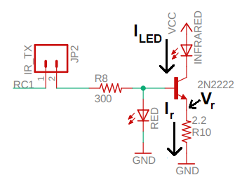
In this transistor circuit the IR LED and resistor currents are almost the same. In other words we will assume that ILED = Ir. Hence, the resistor current is a good proxy for the LED current. We can infer the resistor current by measuring the voltage drop across the resistor and then use Ohm's law to determine the current (because we know the resistance of R10 is 2.2Ω).
In order to measure the voltage drop across R10, setup your oscilloscope as follows:
| Baud Rate | 1200 |
| Ch1 probe | Left side of R10 |
| Ch2 probe | RC1 |
| Ch2 ground clip | Dev board ground loop |
| Horizontal (scale) | 200µs |
| Ch1 (scale) | 0.5V |
| Ch2 (scale) | 1V |
| Trigger mode | Normal |
| Trigger source | 2 |
| Trigger slope | ↓ |
| Trigger level | 1.65V |
- Measure the voltage on the high-side of the 2.2Ω resistor R10
using the oscilloscope by probing the left side of resistor R10 as
shown in the image below. Use the 'p' function in PuTTy to produce
the IR pulses.
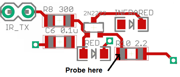
- From this oscilloscope screen shot, what is the voltage drop across resistor when the PWM waveform is at logic 1? You measured this voltage at the "Probe here" location in the image above. Use Ohm's law to compute how much current flows through the IR LED during this brief interval? Round your answer to 2 significant figures.
- If you accidentally placed a steady logic 1 on RC1 (with the
IR_TX jumper installed), the huge current drawn by the IR LED will
cause the Vcc voltage to drop. Let's test this by applying a steady
logic 1 to the IR amplifier
- Remove the IR_TX jumper
- Place one end of a jumper wire to the Vcc pin,
- Briefly place the other end of this jumper wire to the right pin of the IR_TX jumper,
- Record, as your answer to this question, what you observed happen to the green Power-On LED.
| Baud Rate | 1200 |
| Ch1 probe | RC0 |
| Ch1 (scale) | 2V |
| Ch1 ground clip | Development board ground loop |
| Ch2 probe | RC1 |
| Ch2 (scale) | 2V |
| Horizontal (scale) | 200 us |
| Trigger mode | Normal |
| Trigger source | 1 |
| Trigger slope | ↓ |
| Trigger level | 1.65V |
- Replace the "grabber" to the Ch1 oscilloscope probe and connect Ch1 to pin RC0. Capture a screen shot of the 'p' function output as your answer to this question.
- How long does it take, from the start of the IR pulses on RC1, for the output of the IR decoder (shown on RC0) to go to logic 0? How long does it take, from the end of the IR pulses on RC1, for the output of the IR decoder (shown on RC0) to return to logic 1?
We will be using a non-standard data format for our IR data packets - ASCII. When you press the 'S' key to transmit a character, the IR LED will blink at 38KHz. When the IR decoder "sees" this, it's output will go to logic 0.a The 'S' function times the IR LED blinking so that the IR decoder output generates an acceptable looking serial ASCII character. Before using an oscilloscope to examine the signals, I'd like you to look at the code first and predict what you should see on the oscilloscope (and then use an oscilloscope to check your assumptions). Open up the inLab06 code and find the code associated with the 'S' key. Use this section of code to answer the following questions.
-
Each bit of the the variable "letter" is held for some duration of
time using a TMR1 delay loop.
Using the default value for the baudRateSelected variable and the
configuration for TMR1, what is the length of the delay for the code
snippet? What Baud rate does this correspond to?
	TMR1_WriteTimer(0x10000 - bitPeriod[baudRateSelected]);
	PIR1bits.TMR1IF = 0;
	while (TMR1_HasOverflowed() == false);
The instruction EPWM2_LoadDutyValue(LED_ON); makes the IR LED to oscillate
at 38kHz causing the IR decoder to output a logic 0. The instruction
EPWM2_LoadDutyValue(LED_OFF); stops the IR LED from emitting IR radiation
causing the IR decoder to output logic 1.
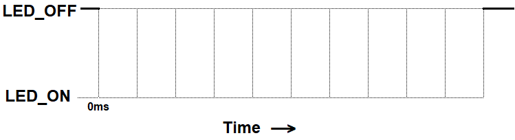
- Let the variable "letter" equal ASCII '5'. Use the code in the "S"
function to trace out the activity that this IR LED would cause on the
output of the IR decoder. Note, the S function transmits 10-bits of data -
make sure to include all of them in your answer. The space between a pair of
vertical dotted lines denotes 1 bitPeriod, the duration of which you found
in the previous problem. Label the time axis at each of the vertical lines
with the the time in milliseconds (to 2 significant digits).
| Baud Rate | 1200 |
| Ch1 probe | RC0 |
| Ch1 ground clip | Dev board ground loop |
| Ch1 probe | RC1 |
| Horizontal (scale) | 1ms |
| Ch1 (scale) | 1V |
| Ch2 (scale) | 1V |
| Trigger mode | Auto |
| Trigger source | 1 |
| Trigger slope | ↓ |
| Trigger level | 1.5V |
- Align Ch 1 on the second lowest reticule,
- Align the horizontal position at the second left-most reticule,
- Align Ch 1 on the second lowest reticule on the upper half of the oscilloscope screen.
- Convert serial stream
[Serial] → Mode → UART/RS232
[Serial] → Serial → Serial 1: UART/RS232 ✓
[Serial] → Signals → Rx → 1
[Serial] → Signals → Threshold → (Trigger Level) → 1.65V
[Serial] → Bus Config → #Bits → 8
[Serial] → Bus Config → Parity → None
[Serial] → Bus Config → Baud Rate → Baud → 1200 b/s
[Serial] → Bus Config → Polarity → Idle high
[Serial] → Bus Config → Bit Order → LSB
[Serial] → settings → Base → ASCII
- Clear all menus off the bottom of the screen
[↑Back] - Screen shot the screen on USB:
[Save] → Save → Format → 24-bit Bit... (*.bmp) [Save] → Save → Press to Save
- Screen capture a transmitted character "5".
- In main.c, find the code under "case 'b':" and set the correct values for the SPBRGH2:SPBRGH registers using the values you found in a previous inLab question. Cut and paste your code for "case '0':" through "case '4':" as your answer to this question.
- In main.c, find the values for the bitPeriod array at the top of main. Set the correct values for the delays using the values you found in a previous inLab question. Cut and paste your code the correct initialized values as your answer to this question.
- Experiment with the Baud rate using the "b" function. What is the fastest, reliable, Baud rate?
- Explain what device is limiting the Baud rate, and how you figured this out. Hint, discuss the relationship between the IR pulses on RC1 and the incoming data on RC0 that you investigated in questions 18 and 19.
When all bits of the character have been shifted in, they are immediately transferred to a two character First-In-First-Out (FIFO) memory. The FIFO buffering allows reception of two complete characters and the start of a third character before software must start servicing the EUSART receiver. Access to the received data is via the RCREG2 register.This means that when you read RCREG2, you may not be reading the most recent character received, but rather something older. To prevent this causing problems, I read the RCREG2 twice at the beginning of main.
- Where in main, at start-up, is the contents of RCREG2 register cleared? State your answer in terms of code line numbers. Hint, I clear the register twice in order to make sure the FIFO is empty. In this weeks lab you will write an ISR to service EUSART2 interrupt. In order to understand how data is collected, how interrupt flag is set and how that interrupt flag is cleared, you will need to read and understand the material in section 16.1.2 of the PIC18(L)F2X/4XK22 Data Sheet posted on the class web page.
- Use the content of the data sheet to help answer the following question.
In particular the introduction to section 16.1.2, section 16.1.2.2 and
sections 16.1.2.4.
- What does FIFO stand for?
- How many complete characters can be stored in the FIFO?
- What register would you read to remove characters from the EUSART2 FIFO?
- Assume that the RSR received the character 'a' and then latter receive the character 'b'. What character would you expect when you read the register in the previous question? What character would you get on the second read? Hint, think about the meaning of FIFO.
- What flag is set when a character is received? Include the name of the register and name of the field.
- When will this flag be set? Hint, section 16.1.2.4.
- Can your program clear this flag by writing 0 to it?
- How does your program clear this flag?