The DRAIN Head Dependent Flux function uses the elevation of the drain as the
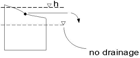
head that controls flow to the drain (e.g. the drain is
at atmospheric pressure). Also water is ONLY ALLOWED
to flow OUT of the groundwater system
Consider the flow, QD, into a drain as a function of head, h, in a cell where
the elevation of the drain is d and the conductance is CD.

FLOW IS NEVER INTO THE MODEL, IT IS ALWAYS INTO THE DRAIN i.e. OUT OF THE MODEL
Notice that flow will be toward the drain, thus it will be at the location of
lowest head in the grid cell

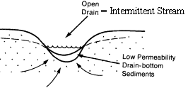
Conceptually, the drain may be buried:

or, an open ditch:

CONSIDER DRAIN CONDUCTANCE
Recall that MODFLOW requires that the user input a variable that represents
all of Darcy's Law except the head difference for Head Dependent Flux boundaries.
So for:
Q = KA dh/dl
Conductance = KA / dl
then MODFLOW calculates the flow as: Q = C dh
Conductance of the river bed is calculated as KA/L, that is:
Kof material over which the gradient is calculated
* area of flow (the cylindrical area midway between
where the heads used for the gradient are located* length of the drain)
/ resistive material thickness (the distance between
locations where the heads used in the gradient calculation)
- if
the backfill K is high relative to grid block (the typical situation),
then assume the average head in the grid cell is 1/2 way between drain and
the grid block boundary and use the grid block K to calculate conductance.
if backfill K low relative to grid block, then
we can assume little loss of head in the grid cell material, thus the average
head in the grid cell applies at the edge of the material surrounding the
drain C should include only backfill K
A drain can be used to represent an intermittent stream
that only gains from the groundwater and never loses. That is, there
is no external source of surface water.
A drain can be used to represent an artesian well.
It may even be located in a deep layer and flow uncontrolled at the surface.
If appropriate, a portion of that flow can be recharged to the shallow system.
MODFLOW 2000 allows the user to specify a fraction (between 0 and 1.0) of the
drain outflow to be returned as recharge to a specified cell.
The drain package can also be used to represent springs
because head can be set at the ground elevation and outflow will occur when
the water table reaches, or rises above, the ground surface, but inflow will
never occur.

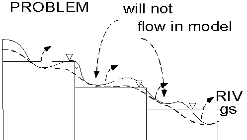
One needs to carefully consider the position of the spring in the cell. If the
spring is located at the upslope end of the cell, then average head in the cell
may not yield outflow, when outflow would occur in the field. This can be visualized
by viewing the diagram below and noticing the solid wavy line as the ground
surface, the dashed wavy line as the field water level and the blocky step function
as the average water level computed for the cell by MODFLOW. Notice that two
of the springs would not flow. This can be dealt with by using a finer grid
or by adjusting the spring elevations to pseudo values. I do not care for the
latter approach. If you choose such an approach, be sure to develop sound reasoning
and present it in your approach. Presenting your reasoning for approximations
is an essential part of a report on a ground-water modeling project.


