In the console area at the bottom of the MPLab X window you should
see the following activity in a tab labeled "SNAP".
*****************************************************


Connecting to MPLAB Snap...

Currently loaded versions:
Application version............00.03.23
Boot version...................01.00.00
Script version.................00.04.48
Script build number............7acb7c9d66
Tool pack version .............1.7.510
Connecting to MPLAB Snap...

Currently loaded versions:
Boot version...................01.00.00
Updating firmware application...
Connecting to MPLAB Snap...

Currently loaded versions:
Application version............00.04.50
Boot version...................01.00.00
Script version.................00.04.48
Script build number............7acb7c9d66
Tool pack version .............1.7.510
Target device PIC18F25K22 found.
Device Id Revision = 0x5

Calculating memory ranges for operation...

Erasing...

The following memory area(s) will be programmed:
program memory: start address = 0x0, end address = 0x273f
program memory: start address = 0x7500, end address = 0x7fff
configuration memory

Programming/Verify complete
If you get an error while programming:
- Make sure that the development board is powered on with
the USB mini cable.
- Make sure that you have configured MPLab correctly.
Subsystem tests
You are going to work through each of the subsystems on your development
board and test them one at a time. After soldering in a new component,
it would be a good idea to re-run all the subsystem tests to check that
you did not create a problem with the added component. This type
of testing is called regression testing.
While testing you PIC may hang for a variety of reasons. You can reset
the PIC processor by pressing the RESET button located at the top of the
development board. You will know that you have
reset the PIC when you are greeted by the splash screen:
Dev'21 Board
Test Program
Spring 2021
Colorado School of Mines - EENG 383
When performing a reset, it's normal to get some garbage characters at
the start of the splash screen - this is just the baud-rate generator
inside the USART subsystem converging to proper frequency.
Test #1 - Test RS232 communication
Soldering:
No additional through-hole components should be soldered to the
development board in this test.
Procedure:
You have already downloaded the test application written to
exercise most of the modules on the development board, now it's
time to use this application to complete testing of your board.
Let's start by running the test application using the following
steps.
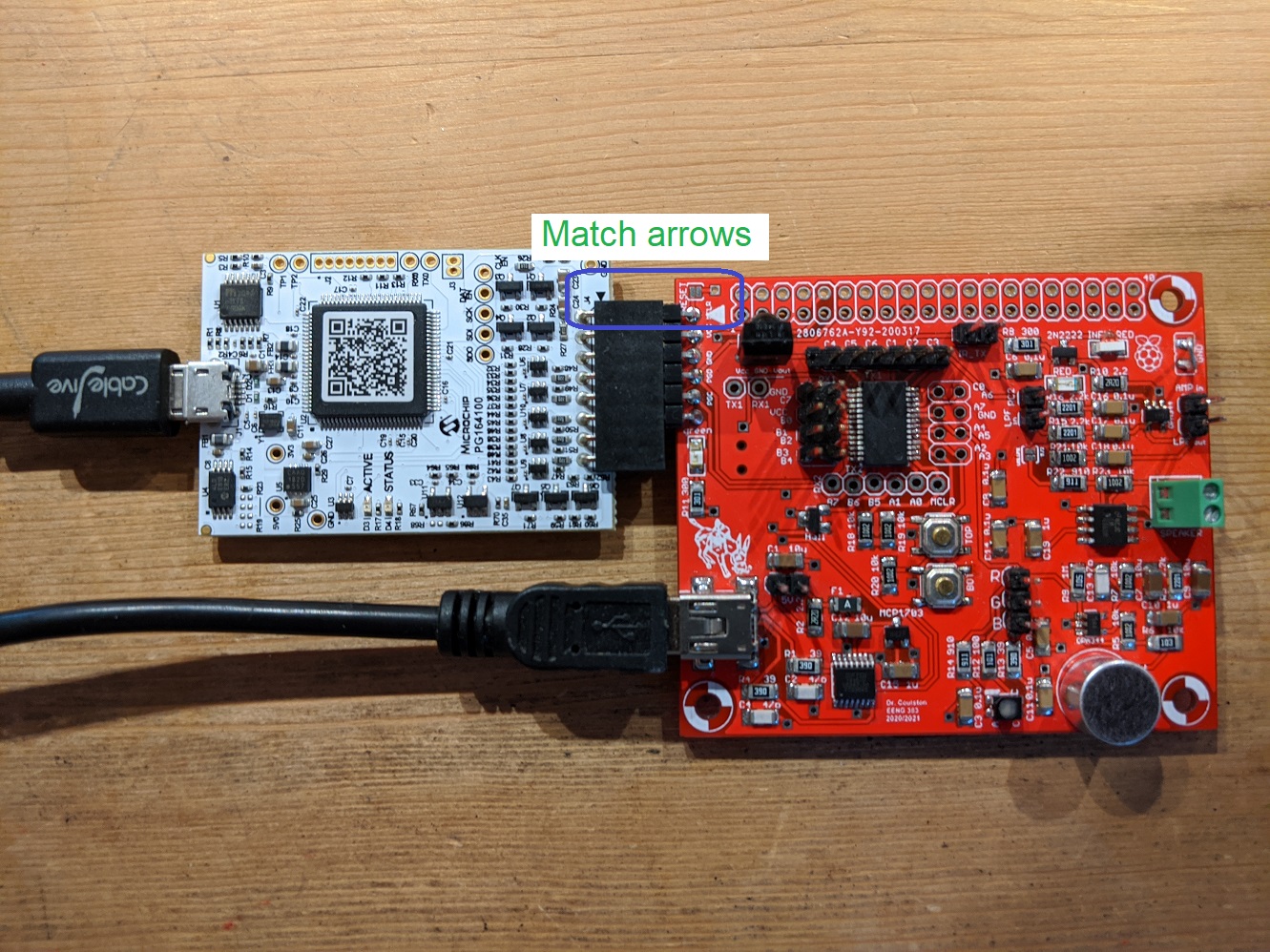
- Unplug both the development board and the SNAP programmer from your PC.
Since the PIC18F25K22 is a flashed based part, its non-volatile memory will
hold the test application until you overwrite it in lab 2. Set the
SPAN programmer aside, you will not need it again in this lab.
- Connect the development board to the PC through the mini-USB connector.
If the sound on your PC is turned on, the PC will make a chime when the
development board is plugged in.
- Find out which COM port is being used by the FT230 chip. You
can do this is a multitude of ways, one of which is by running
Brandon's COM port Sniffer,
Take a screen shot of Brandon's COM port Sniffer by pressing Alt-PrtSc.
This keypress sequence captures the active window to an image buffer. Paste
the image buffer into a document using Ctrl-v. Use this as your answer to Test #1
- Launch PuTTy
Connection type: Serial
Serial line: COMx (where x is the port associated with the FT230
Speed: 9600 (the default)
Open
- Type "?" in the PuTTy window.
This test hex file will bring up an interactive terminal application on
virtual COM port. You should see:
==============================================================
?: help menu
o: k
Z: reset processor
z: clear the terminal
b: Button test.
l: Low pass filter (LPF) test.
a  Amplifier test.
d: ir Decoder test.
m: Microphone test
c: rgb Color test.
t: ir led Transmitter test.
h: Hall effect sensor test.
i: Initialize sd card.
s: read/write SD card.
==============================================================
The prompt, "CMD>" is telling you that the PIC is waiting for a
command corresponding to one of the letters in the leftmost column.
Anytime that you want see the menu, press "?". The PIC is not
a very fast processor and if you press two keys in quick succession,
you may hang the processor - sad but true. If this happen reset the
PIC using the reset procedure outlined in the Subsystems tests section
just below.
For the time being it would be a good idea not to explore these options
as some of them require you to solder and configure jumper wires.
Test #2 - Test CPU
Soldering:
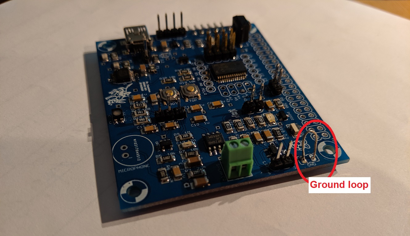
Take a moment and solder ground loops to the PCB. I've found that the
leads of a through hole resistor make great wire for the ground loop -
don't feel bad trashing a resistor for this, they are cheap. When
complete, your ground loops should look like the image
below (note this is a picture of a partially assembled board, yours will
be complete). Ground loops allow you to attach the ground lead clip of an
oscilloscope to your board - super handy.
Procedure:
Once you have the ground loop in, let's test them out by checking if
the PIC is running. To do this follow these oscilloscope instructions.
Note, you will have to remove the "gripper" form the end of the scope
probe and insert the sharp end of the of the probe into the break-out
holes around the PIC.
| Ch1 probe | RB6
|
| Ch2 probe | RB7
|
| Ch1 ground clip | Dev board ground loop
|
| Horizontal (scale) | 500 us
|
| Ch1 (scale) | 2V
|
| Ch2 (scale) | 2V
|
| Trigger mode | Auto
|
| Trigger source | 1
|
| Trigger slope | ↑
|
| Trigger level | 1.2V
|
Make sure that
- Aligning Ch 1 and Ch2 on the second lowest reticules
on their respective halves of the screen,
- Align the horizontal position at the second left-most reticule,
- Clear all menus off the bottom of the screen
[↑Back]
- Since the two channels are not synchronized, you may need to
tell the oscilloscope to stop refreshing the screen. To do this:
Run Control → Run/Stop (the button will illuminate red)
To resume refreshing the screen press the Run/Stop button again
causing the button to be illuminated green.
When you do this you should see something similar to the following. Note
that the frequencies will be different from that shown in the image
below. Channel 1 will be around 515Hz. Channel 2 should be around 5.2kHz.
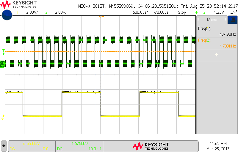
Capture this oscilloscope trace onto a USB drive and then use this image
as the answer to Test #2.
Test #3 - Test Terminal
Soldering:
No additional through-hole components should be soldered to the development
board in this test.
Procedure:
Since you already got the menu to work, this test is a little silly,
but hey the menu options are there. So go ahead and
press "o", the PIC should respond
with the letter "k". This is the most basic test of the PICs
ability to read and write information over its universal
asynchronous synchronous receive transmit (USART) port.
You can also experiment with "z" and "Z" to clear the screen and reset
the processor. Note that the "Z" reset is called a soft reset because
it occurs from within code. If the PIC is hung, then this option will
not be available and you will have to press the reset button at the top
of the board.
The "Z" function performs a reset of the PIC. This is handy when you
may have messed up some registers and just want them back to their
default values. Make a screen shot of the PuTTY window right after
pressing the "Z" key as your answer to Test #3.
Test #4 - Test Buttons
Soldering:
No additional through-hole components should be soldered to the development
board in this test.
Procedure:
When you press "b" at the command prompt, you will see the following
message:
CMD> b
    Button test
    Press any key to exit.
    Press the upper, lower, or both buttons.
Each time one or both button is pressed a message will appear in
the terminal.
Clear the PuTTY window using "z" and then enter the button test
function. Press the upper button three times, the lower button
once, then both buttons once. Then make a screen shot of the PuTTY
window as your answer to Test #4. You have to fast on that last
pair button press. Keep at it, you'll get it!
Test #5 - Test Hall effect sensor
Soldering:
No through-hole components should be soldered to the development board
in this test.
Procedure:
When you press "h" at the command prompt, the PIC will test the
Hall effect sensor. A hall effect sensor is a device which outputs
a voltage proportional to the magnetic field present at the ICs
surface. When pressed you should see the following:
CMD> h
    Hall effect sensor test
    Wave north and south poles of magnet above Hall effect sensor.
    Press any key to exit.
Placing the north or south facing magnetic field of your magnet
will elicit a message on the terminal.
Clear the PuTTY window using "z" and then enter the Hall effect
function. Create at least 3 magnet encounters with the sensor and
show at least one change from North to South pole. Then make a screen
shot of the PuTTY window as your answer to Test #5.
Test #6 - Test Microphone
Soldering:
No through-hole components should be soldered to the development board
in this test.
Procedure
When you press "m" at the command prompt, the PIC will test the
microphone. The microphone continuously provides the amplitude of the
sound wave to the PIC which when it samples the sound wave converts this
amplitude into an 8-bit value between 0 and 255. This function provides
16 samples, each 100uS apart. The samples are collected as soon as
you press a key (after pressing "m"). This allows you to start your
whistle and get it going before it is sampled. An example of the
test output is shown below.
CMD> m
    Microphone test
    While whistling near the mic, press any key.
    Sampled every 100uS.
    MIC:
    73 44 65 127 176 176 121 59 35 66 127 171 152 89 33 22
The output looks a little random, so you will want to plot the samples in Excel
in order to make more sense of them. The image below shows the resulting
plot and definitely reveals the sinusoidal nature of a whistle.
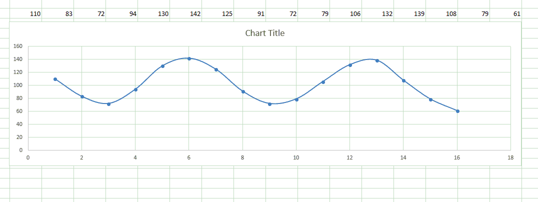
Since we know the samples are taken every 100us, the period of my whistle
is about 700us which corresponds to 1.4kHz, a reasonable value for a
whistle.
The samples are biased around the mid range value of 128. The louder
your whistle, the higher the amplitude of the waveform. If you whistle
too loud or too close to the microphone, you will saturate the microphone
output at 0 and 255. When plotted saturated volume will appear as flat peaks.
The answer for this test requires several steps:
- Whistle near the MIC using the "m" function to collect 16 samples.
- Select the sample in PuTTY (this automatically puts them into the
copy/paste buffer.
- Open Excel
- Paste the microphone samples into a cell.
- Use the Data → Text To Columns function to separate the 16
values into individual cells. You will need to select Delimited, Space,
General as the steps in the Convert Text to Columns Wizard.
- Select the 16 columns containing the data,
- Insert → Charts → Scatter → Scatter with Smooth Lines and Markers
- Change the title of your graph to "Name's Whistle is x.ykHz", where
Name is your name and x.ykHz is the frequency of your whistle.
Copy and paste your graph as the answer to Test #6.
Test #7 - Test Remote Control Receiver
Soldering:
No through-hole components should be soldered to the development board
in this test.
Procedure:
When you press "d" at the command prompt, the PIC will test the
remote control decoder. The IR remote control decoder sensor is able
to translate the IR energy emitted by most remote controls
into a series of logic-level pulses. This little application will
tell you the length of the first 16 of these pulses. After hitting
"d" at the command prompt, grab any handy remote control, point it
towards the dome shape on the IR decoder and press a button. You
should immediately see a series of numbers appear on your terminal.
For example, pressing the OFF button on my RoKU remote produced the
following output.
CMD> d
    IR decoder test
    Press a IR remote control button.
    Press any key to exit.
    bit     high    low
    0:      0       4647
    1:      23b4    464
    2:      448     473
    3:      d13     47b
    4:      442     46f
    5:      d19     474
    6:      442     485
    7:      d0d     470
    8:      d1b     472
    9:      d12     46e
    10:     457     46f
    11:     d27     471
    12:     445     461
    13:     456     471
    14:     450     476
    15:     44f     476
    Done decoding IR packet.
Note that some cell phone emit IR signals for a variety of reasons.
Make sure that all nearby cell phones are stowed away before starting
this test, otherwise you will get unpredictable results.
Clear the PuTTY window using "z" and then enter the remote control
decoder function. Find a remote and press a button to produce a
control sequence. Make a screen
shot of the PuTTY window as your answer to Test #7.
Test #8 - Test IR LED Transmission
Soldering:
No through-hole components should be soldered to the development board
in this test.
Procedure:
When you press "t" at the command prompt, the PIC will test the
IR LED and driver. When you press "t", you will be presented with
the following options - these used to control the projector in
Brown 305. The projector was moved out during the summer :(
Connect jumper over IR_TX header.
Select the index of the command to send from the following list:
    0  OFF
    1  ON
    2  MAG+
    3  PIC MUTE
    4  PG UP
    5  MAG-
    6  PG DOWN
    7  MENU
    8  UP
    9  LEFT
Before performing this test please make sure that you place jumpers across
the 5v jumper pins near the USB connector. This jumper will
help ensure that operating the IR LED doesn’t brown out the PIC.
Also place a separate jumper across the IR_TX header. This
jumper will enable the PIC to control the IR LED.
When you issue the "t" command from command prompt the PIC will ask
you what IR command you want to send to the projector that used to
be in Brown 305. Instead of the projector, you will use an oscilloscope
connected to the IR Remote Control Receiver output. Do this as follows.
Connect an oscilloscope probe to channel 1. Connect the ground clip
of the oscilloscope to the ground loop you soldered in for Test #5.
Use the oscilloscope probes gripper to attached to the RC0 header
pin that you just soldered in.
| Ch1 probe | RC0
|
| Ch1 ground clip | Dev board ground loop
|
| Horizontal (scale) | 10ms
|
| Ch1 (scale) | 1V
|
| Trigger mode | Normal
|
| Trigger source | 1
|
| Trigger slope | ↓
|
| Trigger level | 1.65V
|
Make sure that
- Aligning Ch 1 is on the second lowest reticule on the screen,
- Align the horizontal position at the second left-most reticule,
- Clear all menus off the bottom of the screen
[↑Back]
- Make sure the Run Control button is is illuminate green.
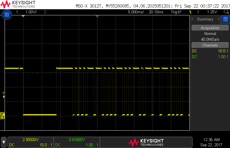
When you do this you should see something similar to the following when
you send a command using the "t" key. Note, the time base is slightly
different.
It's important to remove the jumper from the IR_TX jumper after
you complete this test. This circuit draws a lot of power and may
cause the PIC to brown-out if the jumper is left in place for other
tests.
Clear the PuTTY window using "z" and then enter the IR LED TX function.
Connect an oscilloscope as described in the instructions presented in the
PuTTY. Use a USB drive to capture an image of the captured waveform for
the numeric function corresponding to the least significant digit of your
CWID. Include the oscilloscope image as the answer to Test #8.
Test #9 - Test Low Pass Filter
Soldering:
No through-hole components should be soldered to the development board
in this test.
Procedure:
When you press "l" at the command prompt, the PIC will test the
low pass filter. This test will check that the Low Pass Filter
is functioning correctly. To accomplish this you will connect a PWM
channel to the LPF. You will also connect oscilloscope probe (channel 1) to
the PWM input and an probe (channel 2) to the LPF output to verify
correction operation. When you type "l" at the prompt you will see
the following instructions.
CMD> l
    Low pass filter (LPF) test
    Install jumper over RC2 and LPFin on header.
    Connect oscilloscope channel 1 to PIC header pin C2 (vertical scale 2v/div).
    Connect oscilloscope channel 2 to LPFout pin on header (vertical scale 1v/div).
    Trigger on channel 2.
    Set the horizontal scale to 250ms/div.
    Press upper button to increase frequency.
    Press lower button to decrease frequency.
    Hit any key to exit.
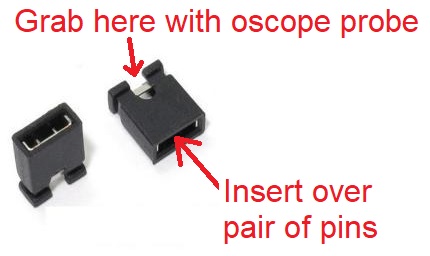
Follow these instructions. When a jumper is placed over a pair of pins,
you can still probe the signal by
attaching an oscilloscope probe to the metal connection shown.
In order to observe the signals being generated, you need to connect MCU
pin RC2 to LPF_in pin of JP2 header with a jumper wire. After you do this
setup your oscilloscope as follows:
| Ch1 probe | RC2
|
| Ch2 probe | LPFout
|
| Ch1 ground clip | Dev board ground loop
|
| Horizontal (scale) | 250 ms
|
| Ch1 (scale) | 2V
|
| Ch2 (scale) | 1V
|
| Trigger mode | Auto
|
| Trigger source | 2
|
| Trigger slope | ↑
|
| Trigger level | 1.2V
|
Make sure that
- Aligning Ch 1 and Ch2 on the second lowest reticules
on their respective halves of the screen,
- Align the horizontal position at the second left-most reticule,
- Clear all menus off the bottom of the screen
[↑Back]
- Since the two channels are not synchronized, you may need to
tell the oscilloscope to stop refreshing the screen. To do this:
Run Control → Run/Stop (the button will illuminate red)
To resume refreshing the screen press the Run/Stop button again
causing the button to be illuminated green.
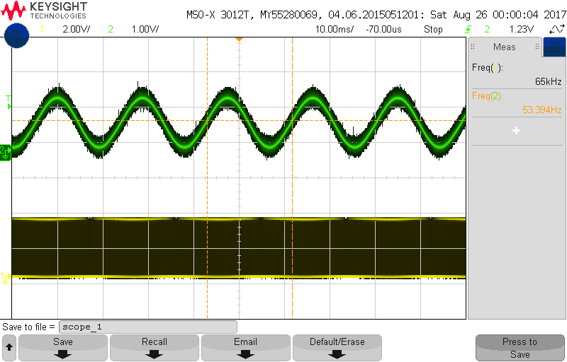
When setup, you should see something like the following on your
oscilloscope. Try pressing the up and down buttons to adjust the
frequency. Each button press should change the frequency up or
down depending on which button is pressed.
Clear the PuTTY window using "z" and then enter the low pass filter function.
Connect an oscilloscope as described in the instructions presented in the
PuTTY. Use a USB drive to capture an image of the captured waveform for
the numeric function after pressing the top button the same number of times
as the least significant digit of your CWID. Include the oscilloscope image
as the answer to Test #9.
Test #10 - Test Amplifier
Soldering:
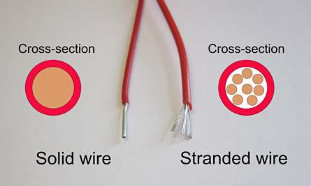
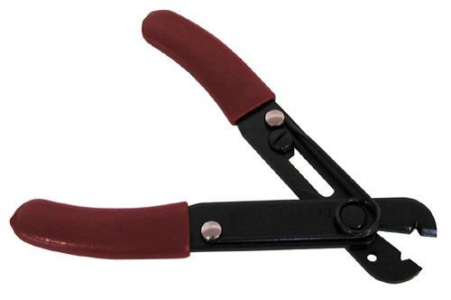
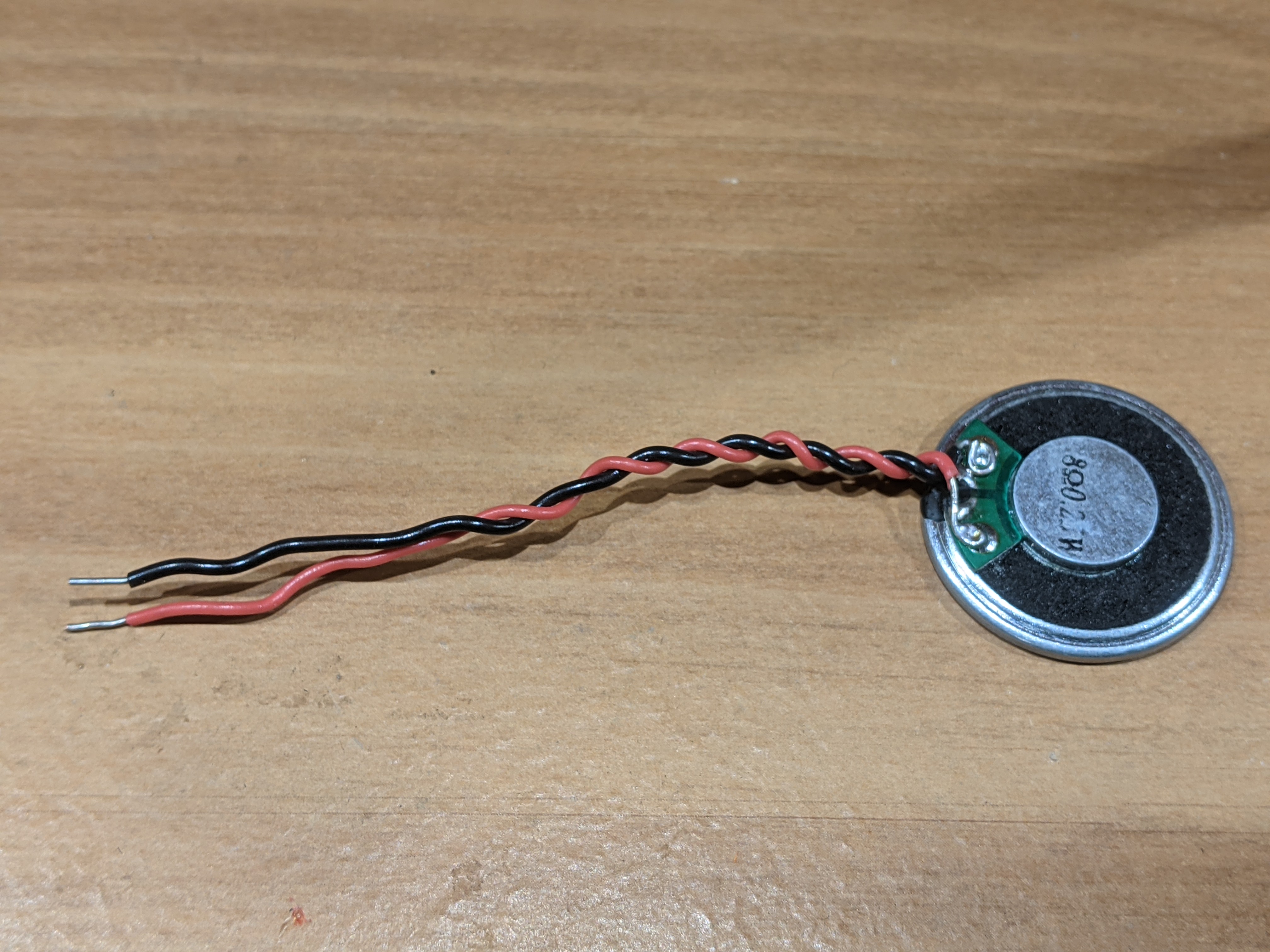
Cut off equal lengths of red and black solid core wire from the lab.
Strip off about 1/4" of wire from both ends of both wires. Use a
pair of needle nose pliers to make a small loop on one end of each
pair. Then solder this loop to the pads on the speaker.
This should look something like the following image.
Insert the exposed ends of wire from the speakers into
green terminal block and tighten the screws on the terminal block to
hold the speaker in place.
Procedure:
When you press "a" at the command prompt, the PIC will test the
audio amplifier. The following instructions tell you how to configure
the development board.
CMD> a
    Amplifier test
    Press any key to exit.
    Connect PIC pin C4 to LPFin pin using a jumper wire.
    Place a jumper over the LPFout/AMPin jumper.
    Place a jumper over JP1 next (it's next to the USB port).
    Connect the speaker to the green terminal block.
    Press the upper button to play the next note from a song.
    Press any key to exit.
The development board comes equipped with a National Semiconductor
LM4862 audio amplifier which will drive the mini speaker.
While the button is held down, the note will play. Releasing the button
moves to the next note which is played when the button is pressed.
You must place a jumper over the 5V jumper when performing
this test, otherwise your PIC will brown-out. This will cause
unpredictable behavior.
It's possible that your development board will brown-out during this
test even with 5V jumper in place. This can happen because the speaker draws
so much power that the Vcc level on the development board drops below
the minimum needed to keep the PIC operating
correctly.
Take a picture of your speaker with soldered wires and include it
as the answer for Test #10.
Test #11 - Test RGB LED
Soldering:
No through-hole components should be soldered to the development board
in this test.
Procedure:
When you press "c" at the command prompt, the PIC will test the
RGB LED, and you will receive the following instruction on where
to place three colored jumper wires in your kit. You may can separate
the jumper wires by peeling them away from one another.
CMD> c
    RGB LED test
    Connect RC2 to R.
    Connect RB0 to G.
    Connect RB5 to B.
    Hit any key to exit.
When you run the RGB test you should note that the
LED cycles through the rainbow colors. Its not an entirely smooth
progression, but should be fairly close.
Take a picture of your development board with all three jumper wires
attached and the RGB LED displaying yellow as your answer for Test #11.