EENG 393
In Lab 11 - Enclosure designRequirements
Working in teams of two, read through the following lab activity and perform all the actions prescribed. There is no deliverable for this inLab, but the instructions contained are essential to completion of the this week's lab, please work through these instructions carefully.Objective
This document outlines how to take an EAGLE layout and use it to build a front panel for your power-supply using our Epilog Legend 36EXT laser cutter. The image below shows a finished front face plate for the power supply that I designed, your will look different to accommodate your circuit. The work-flow to accomplish uses the following software packages, in order, EAGLE CAD, Inkscape, Corel Draw, and a Epilog laser cutter.Face Plate design and laser cutting basics
A front panel serves several roles that factor into your design including: providing access to controls, protecting the user from electrical voltages, providing control information, providing status interpretation, and serving as a form of documentation.Clearly the front panel must be dimensionally accurate, matching the features of the PCB. In order to accomplish this, we will start the design of the front panel using your PCB design in EAGLE CAD.
The input to a laser cutter is a CAD file containing the outline of objects to cut, along with some material, and the output is material cut according to the design in the CAD file. There are a couple of important points that need to be clear before proceeding and these involve how you can control the laser intensity over different objects in your CAD file.
A laser cutter operates in one of two modes, vector or raster. In vector mode the pair of motors controlling the position of the leaser head, move in coordination so that the laser moves smoothly along a lines or arc while lazing material. In vector mode, you can cut clean, smooth circles and lines. In raster mode, the laser sweeps left to right in a row, firing its laser ever where the material is to be marked in that row. The laser continues moving down rows and sweeping until the image specified in the CAD file is rendered on the material. This is much like the old dot-matrix printers from days-gone-by. Rastering operations take far longer then vector operations.
The laser cutter looks at the line widths of the objects in your CAD file to determine whether to render them using vector or raster. Lines draw with a width of 0.0762mm in Inkscape and "Hairline" width in Corel Draw will be rendered using vector operations. Any other width will be rendered using raster.
Most laser cutters have the ability to vary the intensity of the laser beam cutting the material as they process the commands in your CAD file. You will use this to have the laser either cut the material all the way through, or just engrave the material to some small depth. You control the strength of the laser using color; red is high-powered cutting and blue is low-power engraving. Note, that raster graphics are always rendered using the same low-power setting as vector engrave.
Faceplate in EAGLE
In order to create the front panel for your PCB we will create new layers in which we will place specifics types of information.- Launch EAGLE and open the project associated with your PCB,
- Select the layout,
- Open the Layer Setting… tool,
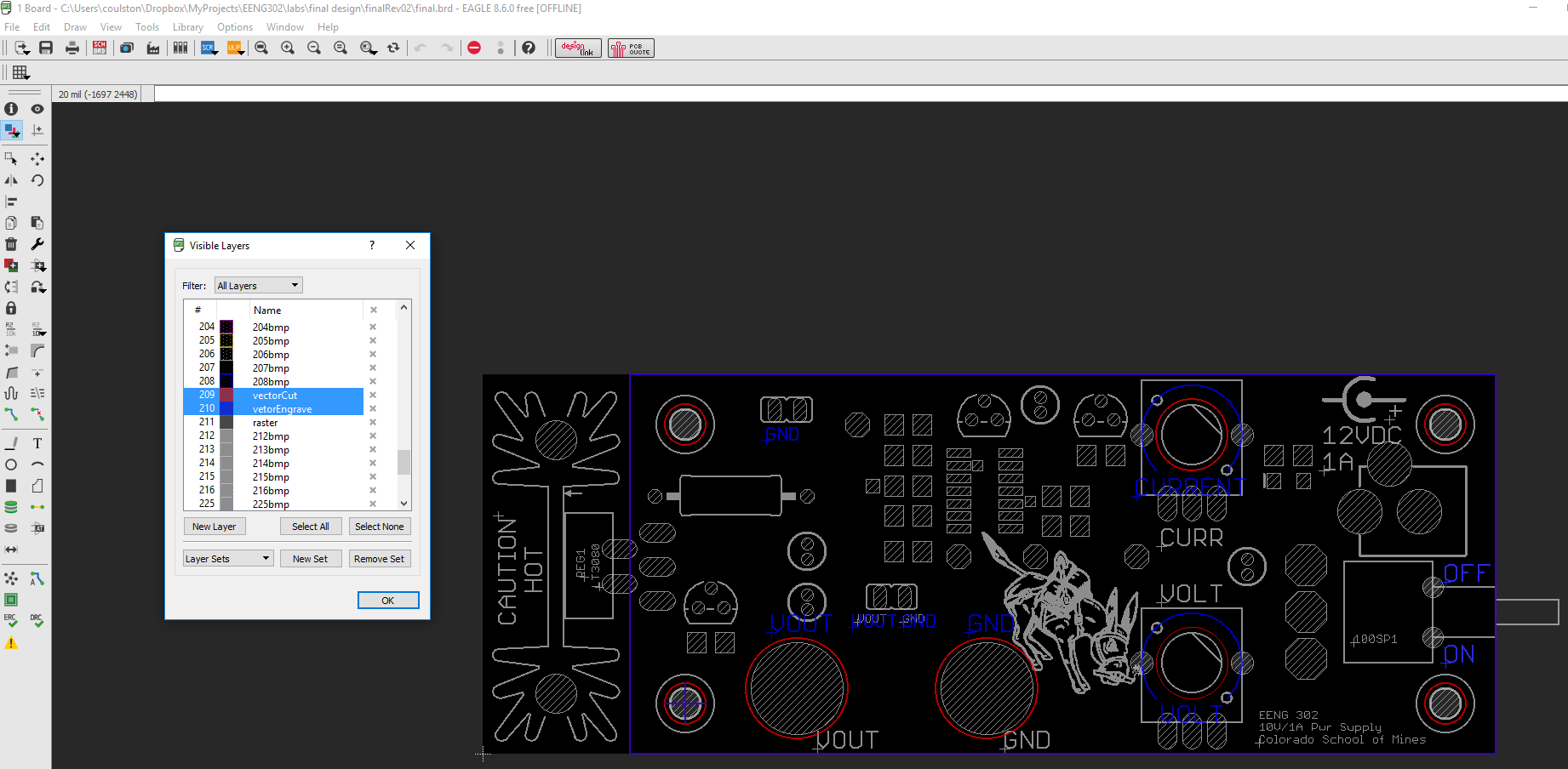
- In the Visible Layers pop-up
- Scroll down to layer 209 If Layer 209 is not aviable, then use layer 234),
- Double click on the 209,
- In the Change Layer pop-up,
- Change the name to "vectorCut"
- Change the color to red (row 2, column 5),
- Check Displayed,
- Click OK.
- Change layer 210 (or 235) If Layer 210 (or 235) is not aviable, then use layer 235),
- vectorEngrave,
- Color: Blue (row 2, column 2),
- Displayed ✓
- Change layer 211If Layer 211 is not aviable, then use layer 236),
- raster,
- Color: Grey (row 8, column 1),
- Displayed ✓
- Add elements to layer 209 (or 234):
- Select layer 209 (or 234) vectorCut from the layer select,
- Select the Line tool,
- Select Wire Bend Style 0 (rectlinear),
- Set Width to 0.07616 mils. Hit enter to set width.
- Click and outline the portion of the PCB you want covered with acrylic (avoid the heat sink),
- Click the Circle tool,
- Click on one of the centers of your mounting holes,
- Drag and set the radius of the hole to 80 mils,
- Include circles around the other three mounting holes,
- Add holes for the potentiometer shafts (radius 140 mils),
- Make room for the spring terminal block (wires and actuation) by modifying the outline of your layer 209 (or 234) cutout or by adding access holes,
- Add holes for the test points,
- Add cut-outs for any other areas that you want access to.
- Add elements to layer 210 (or 235):
- Select layer 210 (or 235) vectorEngrave from the layer select,
- Select the Line tool,
- Select Wire Bend Style 0 (rectlinear),
- Click and outline the 209 (or 234)outline. In other words, cover the red layer 209 (or 234) outline with a blue 210 (or 235) outline,
- Click the Text tool,
- Type "ON" in the Enter test: box,
- Click OK,
- Place the ON text on the side of the ON/OFF switch that corresponds to ON by left mouse clicking,
- Add text for OFF, VOUT, GND, and any other signals that you want to use.
EAGLE export to Inkscape
Now that we have our masks properly sized, we need to export them to Inkscape. We start by "printing" the vectorCut and vectorEngrave layers as pdf files and then import these in Inkscape.- Save the file, File → Save
- Open the Layer Settings… Tool,
- Select "Hide Layers" to remove all layers from being displayed,
- Select layer 209 (or 234), "vectorCut" so only this layer is displayed,
- Click OK to exit the Visible Layers pop-up,
- File → Print…
- In the Print pop-up:
- Scale factor: 1
- Ouput file: <target director> with File name "vectorCut.pdf",
- Save and Overwrite previous version if it exists,
- Click OK to print.
Inkscape import
The real goal of the preceding steps was to generate a pair of CAD files that have perfect dimensional consistency with the PCB.- Launch Inkscape
- File → Import,
- Navigate and select vectorCut.pdf generated in the previous step, click Open
- In the PDF Import Settings, leave the defaults and click OK,
- Use Ctrl-scroll to zoom in and out of the Inkscape canvas,
- Click on any edge in the red vector cut image,
- Object → Ungroup (Shift+Ctrl+G),
- Repeat ungroup around 8 times until the individual elements in the vector cut are separated,
- Select and delete the text "<Date> <Time> <Path><File Name>
- Repeat with vectorEngrave, but place it so that it does not overlap with the vectorCut,
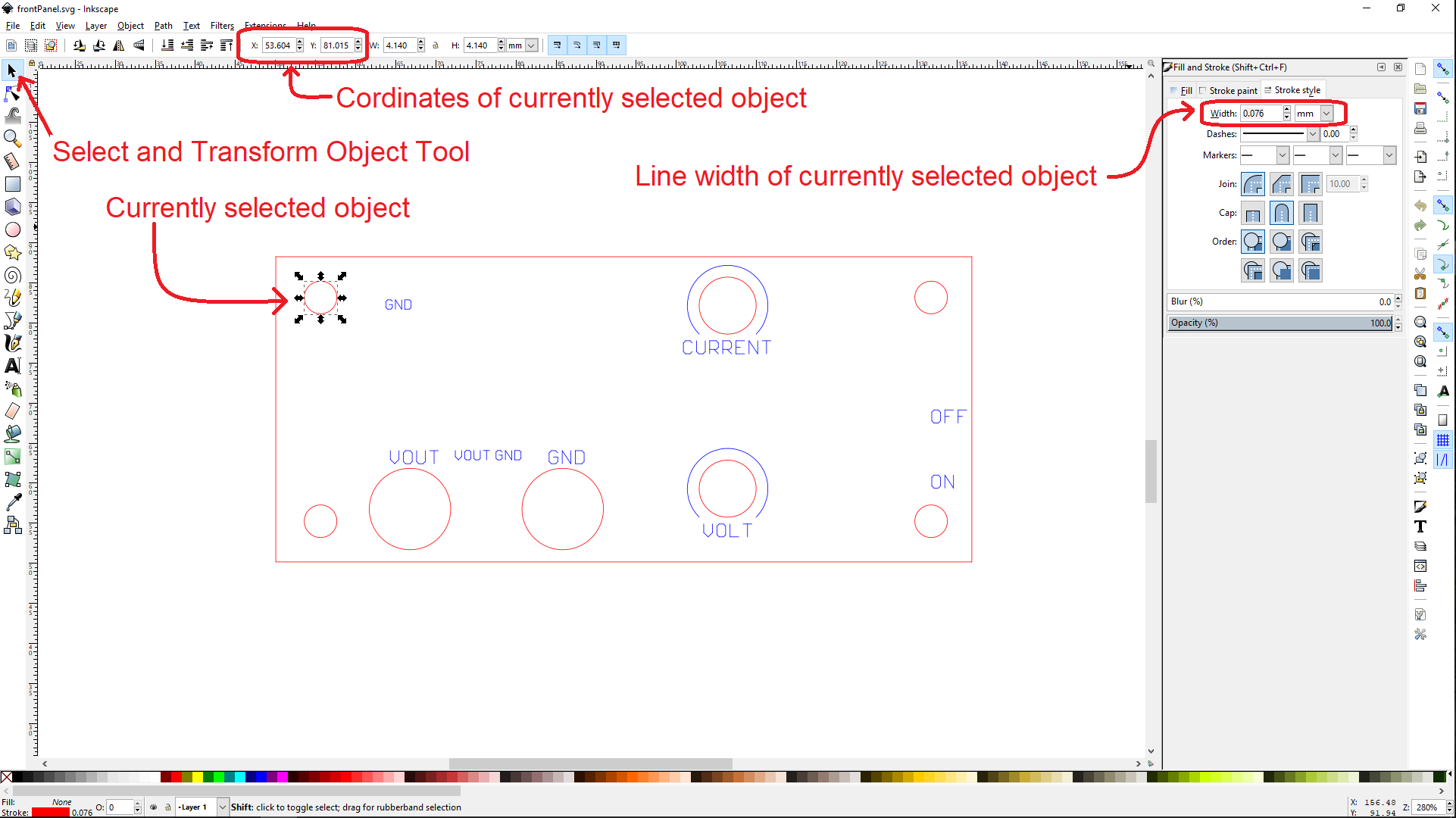
- Select the entire vectorEngrave using the Select And Transform Object Tool,
- Set the X Y coordinates to nice whole round coordinates (50mm,50mm),
- Select the entire vectorCut using the Select And Transform Object Tool (arrow),
- Set the X Y coordinates to the same as those used for the vectorEngrave,
- Select one of the four outline edges,
- Press the Delete key on your keyboard, the blue vectorEngrave line should be removed,
- Delete the other three outline vectorEngrage edges,
Inkscape modification
You need to change the line width to make it very thing so that when you import your design into CorelDraw these "thin lines" will be interperted as "hairlines." We'll explain soon, for now follow these steps.- Select everything using Crtl+A,
- Make sure everything is ungrouped, by typing Shift+Ctrl+G about ten times,
- Right click on any of the selected objects,
- Select "Fill and Stroke",
- In the right window, in the Fill and Stroke panel, select the Stroke style tab,
- Set the width to 0.0762mm.
- Select Text tool
- Change the text size to 12pt
- Click near an existing piece of text that was imported from EAGLE,
- Type the same word that you clicked next to,
- On the right side of the screen, in the Fill and Stroke window
- Select the Fill tab
- Click on the "x" to select no fill - the text will disappear,
- Select the Stroke paint tab
- Select the first square "Flat color"
- Set R=0, G=0, B=255
- Select the Stroke Style tab,
- Set line width to 0.0762mm,
- Click anywhere on the screen to commit changes.
- Delete the imported EAGLE text that you just edited. You may need to move the Inkscape text to do this.
- Minimize the number of different fonts,
- Minimize the number of different font sizes,
- Align vertically and horizontally,
- Provide visual borders for functionally related items,
- Center text with associated control,
- Use your white space,
- Avoid crowding.
Inkscape export
- File → Save
- Save in: Hornet → adit → Documents → EENG383 → lab11
- File name: frontPanel
- Save as type: Inkscape SVG (*.svg)
Corel Draw import
Corel Draw is only available in the Garage, on the computers that run the laser cutters. While Corel Draw is pretty old school, it is the most common graphics program used to run laser cutters. It's not that hard to understand, but these instructions will really help. Note, that the licensed copies of Corel Draw have username: bhaun@mines.edu and password: epilog- Launch Corel Draw
- File → New …
- Layout → Page Layout …
- In the options pop-up, select Page Size in the left submenu,
- Set Width=36" and Height=24",
- Click Ok,
- File → Import,
- Navigate and select frontPanel.svg you just created,
- Click Import,
- Your cursor will change to a frame corner, click the upper left corner in the upper left side of your canvas. Note that the location of your image is where it will be cut on the laser cutting bed.
- To move your cut-out:
- Select all of your design using Edit → Select All → Objects (Ctrl+A),
- Use the Pick Tool (arrow) to drag the image around to where you want it.
- Right click on the border of your cut-out, if Object Properties does not have a check mark next to its left, select it,
- Right click on the border of your cut-out and select Ungroup Object,
- Right click on the border of your cut-out and select Unlock Object,
- Right click on the border of your cut-out and select Ungroup Object,
- Type Ctrl-A to select all the objects in your design, in the Object Properties sub-window make sure that the width is "Hairline". If it is not, just select "Hairline" from the width choices.
- Select each text object object and make sure that it had "No Fill" in both "Fill Type" and "Background Fill Type".
Sending CAD file from Corel Draw to the EPILOG laser cutter
The final step in CAD process is to tell Corel Draw to laser cut your CAD file. Perhaps surprisingly the Epilog laser cutter is seen by the computer as a printed. So let's print your CAD file to the Epilog "printer" using the following commands:- File → Print,
- In the Print pop-up and in the General tab, select Epilog Engraver as the printer,
- Click on the Preferences… button,
- In the EpilogEngraver Properties pop-up shown below, make the
following adjustments:
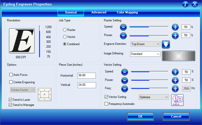
- PieceSize (inches)
Horizontal: 36"
Vertical: 24" - Vector Settings
Setting Acrylic Legend EXT Cardboard Legend EXT Acrylic Fusion M2 (cut) Acrylic Fusion M2 (raster) Cardboard Fusion M2 (cut) Speed 50% 10 90 30 Power 30% 100 60 40 Freq 500Hz 50 Ignored 50
- PieceSize (inches)
- Click OK to leave the EpilogEngraver pop-up,
- Click Print to send your job to the Epilog laser cutter,
Running the EPILOG laser cutter
The Epilog laser cutter in the Mines Garage is a big dangerous, expensive piece of equipment. The main danger from the laser cutter is the myriad of small fires that it creates, not from the laser beam cutting you in half. Consequently, you must be present at all times while the laser is cutting material, no exception grated. If you must leave the laser cutter, open the top cover of the laser cutter and the safety interlocks of the laser cutter will automatically turn off the laser. You can find more information about the laser cutter on the Design LabBasic Procedure
- Focus the laser on your material by adjusting the material deck height,
- Turn on laser pointerm
- "Cut" outline of the shape with lid open,
- Position material so that it move effectively used
- Close lid,
- Cut production file.