EENG 383
In Lab 4 - Music BoxRequirements
Working in teams of two, read through the following lab activity and perform all the actions prescribed. You do not need to document bullet items. Make a record of your response to numbered items and turn them in a single copy as your teams solution on Canvas using the instructions posted there.Include the names of both team members at the top of your solutions. Use complete English sentences when answering questions. If the answer to a question is a table or other piece of art (like an oscilloscope trace or a figure), then include a sentence explaining the piece of art. Only include your answers, do not include the question-text unless it is absolutely needed.
Objective
The objective of this lab is to introduce you to the MPLAB Code Configurator (MCC) and how to use timers to generate delays.External Hardware
Today you will write code that you can interact with through the terminal (input) and generate musical tones through the speaker (output) using timers. Let's start by looking at the speaker and the hardware that will drive it. Start by searching the Internet for the technical documents for the 1" Mallory PSR-28N08A-JQ speaker. Go to http://www.mallory-sonalert.com and search for the product number of the speaker. We will need to use the frequency response graph for the following questions.- Using the Frequency Response graph in the technical documents, at what frequency does the speaker produce the loudest sound and what is the magnitude of this sound (include units)?
- A person with good hearing should be able to detect sounds with a volume level of 70db. What is the lowest frequency, for our speaker, that has this volume level?
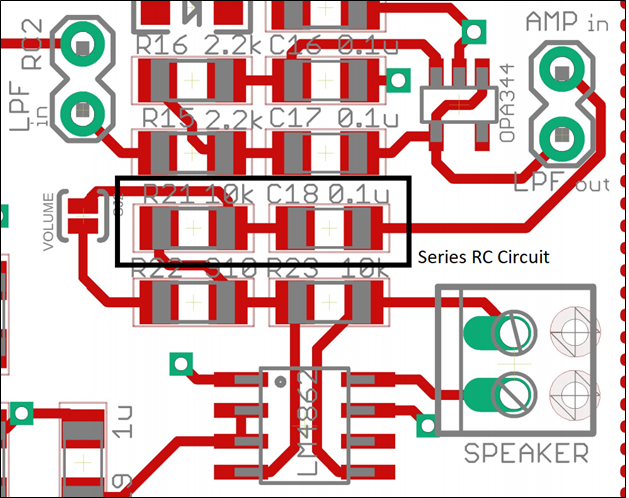
- Pull the technical documents for the LM4862 (audio amp) by looking up its part number from the bill of materials linked in inlab01. On page 1 of the technical documents, Figure 1 shows a typical audio amplifier application. Which pin number and pin name is connected to the audio input through a series RC circuit?
- Look over the schematic and layout of the development board and identify
the silk screened identifier next to the header pin that is connected to
the audio input pin of the LM4862. Hint: Follow the connection from the
LM4862 pin past the series RC circuit. See the image below if you still
need help.
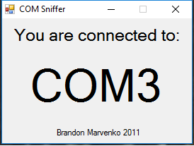
When you plug your development board into a PC you may have noticed that your PC makes a chime sound. This chime tells you that the PC has recognized your development board and assigned it a COM port. A PC may have any number of COM ports, so each is given a unique numerical value. There are a variety of different ways to determine the COM port assigned to your FT230 chip, but I find the easiest to run Brandon's COM port finder. There is also a link to this application on the class main page. When your board is connected to a PC through a USB cable, running COMSniffer should produce output similar to the following; in this case my development board was assigned COM3. Note that more than likely your PC will assign your development board a different port number. You will need the port number anytime you need to connect your PIC to a terminal application like PuTTY.
Internal Subsystem
We will hold off exploring the The Enhanced Universal Synchronous Asynchronous Receiver Transmitter (EUSART) subsystem of the PIC until next week's lab. Instead we will focus on the big idea in today's lab, interrupts.The internal configuration bits for the PIC are contained in the special function registers (SFR). You can manipulate the values of the bits in these registers in your C programs by concatenating the register NAME with the FIELD name in the format NAMEbits.FIELD = value;, the expression "bits" needs to be appended to the register NAME and the "." separates the NAME and FIELD. Let's look at a practical example; open the Microchips PIC18(L)F2X/4XK22 Data Sheet to page 166. Let's say that you wanted to enable timer 1 by setting the TMR1ON field of the T1CON register. In your C code you would add the line T1CONbits.TMR1ON = 1;
- To enable Timer 1 to run off Fosc/4 mode using a 1:1 prescaler, how
do we need to configure the following T1CON bits?
- T1CONbits.TMR1ON =
- T1CONbits.TMR1CS =
- T1CONbits.T1CKPS =
Firmware Organization
A microcontroller by itself is not terribly interesting, being not much more than a slow-running processor. Microcontrollers derive their power from the subsystems they contain and the external devices these subsystems can control. In order to be able to interface to as many different external devices as possible, the computer engineers who design microcontollers make the subsystems as flexible as possible. This means that there are potentially a great number of alternative configurations for each subsystem. When developing an embedded application that interfaces microcontroller subsystem to an external device, one of the first tasks you must complete is configuring the subsystem.In my experience, subsystem configuration is a necessary task that can turn into a time consuming and potentially-frustrating challenge Thankfully, the folks at Microchips developed the MPLAB Code Configurator (MCC) to address this challenge. Paraphrasing the text in the MPLAB® Code Configurator User’s Guide, MCC is a plug-in tool in MPLAB X which generates drivers (software) for controlling and driving subsystems based on the settings and selections made in the Graphical User Interface. The generated drivers can be used in your program.
Create new project
The first step to using MCC is to create a new project and launch MCC as described in the steps below.- Launch MPLab X
- Close any open project: File → Close All Projects
- Create a new inLab04 project as you did in Lab 2. Make sure, at step 2 (Select Device), to choose PICKit 3 or 4.
- Click Tools → Embedded → MPLab Code Configurator
- If the MPLab Code Configurator is not listed then you will need
to install the Code Configurator as follows:
- Tools → Plugins
- In the Plugins pop-up select the "Available Plugins" tab
- Check the "MPLab Code Configurator" check box
- Click Install
Configure the PIC with MCC
You should use MCC for the remainder of the term for all future projects. Every project in this class will require you to configure the oscillator and I/O pins. In addition to these two subsystems, you will also configure the timer subsystem in the steps below.- In the INTERNAL OSCILLATOR area of the System Module window
- Oscillator Select: Internal oscillator block
- System Clock Select: FOSC
- Internal Clock: 16MHz_HFINTOSC
- Software PLL Enabled: Check
- In the Pin Manager: Grid [MCC] tab of the console window click on the open lock in the PortB 5 column and in the output row. The blue background color should switch to green, meaning that RB5 is now an output. The open lock immediately below should change its background color to orange meaning that RB5 is not an input.
- In the Project Resources area of the project window, click "Pin Module". The editor window will change from the System Module to Pin Module. Click on the Custom Name text box in the RB5 row and change the name of RB5 to "SPEAKER_PIN"
- Make pin RA6 an output called "TEST_PIN"
- In the Device Resources area of the project window, expand the Timer option. Double click TMR1.
- In the Device Resources area of the project manager window, expand
the "Timer" selection and double click on TMR1. The Easy Setup tab of the
editor window should change to a TMR1 view. Make sure the following items
are selected (leave the other defaults alone),
- Enable Timer: ✓
- Clock Source: FOSC/4
- Prescaler: 1:1
- Enable Timer Interrupt: ✓
- In the Device Resources area of the project window, expand the EUSART option. Double click EUSART1.
- In the Project Resources area of the project window click on EUSART1.
- Enable EUSART: ✓
- Enable Transmit: ✓
- Enable Wake-up: □
- Auto-Baud Detection: □
- Enable Address Detect: □
- Baud Rate: 9600
- Transmission Bits: 8-bit
- Reception Bits: 8-bit
- Clock Polarity: async_noninverted_sync_fallingedge
- Enable Receive: ✓
- Enable EUSART Interuupts: □
- Redirect STDIO to USART ✓
- File → Save All, or click on the Save All (disk icon) in the toolbar. Keep the default name "myConfig.mc3",
- Click on the "Generate" button in the Project Resources area of the project manager window. If you select the Output → MPLAB Code Configurator tab, you can keep an eye on what files MCC is generating and updating. Note that anytime that you make a change to the configuration using MCC, you need to save and re-generate the supporting files exported into your project.
- Click the project tab in the project manager area. Expand the "Source File" folder.
- Double click the file main.c to open it in the editor window.
- Replace the contents of main.c with inlab04.c
- What two EUSART1.c functions are being used just inside the infinte loop in main?
- Write out the two calls to TMR1_SetInterruptHandler and in what functions each call occured.
- The second call to TMR1_SetInterruptHandler will be the one used by your program. What ISR will your program use to service the TMR1 interrupt?
-
When answering the following questions, focus on the interrupt handler
not calls to the WriteTimer function.
- What is the daughter function of INTERRUPT_InterruptManager?
- What is the granddaughter function of INTERRUPT_InterruptManager?
- What does the daughter function do to TMR1IF and to the value of TMR1?
- Where is the variable timer1ReloadVal given a value? What is this value? Note the initial value is set by MCC in the Timer Period field in the TMR1 Easy Setup window.
When the TMR1 interrupt occurs, the INTERRUPT_InterruptManager function (you can find it in the MCC Generated File interrupt_manager.c) is invoked by the PIC. Find the INTERRUPT_InterruptManager function and name the function that it calls. Call this the daughter function of INTERRUPT_InterruptManager. To find the granddaughter function of the INTERRUPT_InterruptManager function look at the code associated with the daughter function of the INTERRUPT_InterruptManager function. When you are looking for a MCC function, the first word of the function is the name of its MCC Generated File. This code in the daughter function looks like it calls TMR1_InterruptHandler(), but this "function" is really a function pointer - note that the TMR1_InterruptHandler variable is true. A function pointer is variable that can be assigned to a function. In our case the TMR1_SetInterruptHandler function performs this assignment by taking in as an argument, the function you would like to serve as the interrupt service routine for TMR1. The TMR1_SetInterruptHandler function is called in two separate placed.
- What is the first and last thing that happen in this function? Ignore variable declarations.
- A flag is a variable (usually typed uint8_t) that equals either true or false. What three flags are checked in this function? Briefly explain what each flag does.
- What behavior would you expect if you removed the incNote=false; statement from the function. Hint, consider what would happen if playNote was true (a note is being played) and the user typed "i" in at the terminal. Heck, give it a try (by commenting out the statement) if you want to check your answer.
Firmware Operation
Your next step will be to download, run and observe the behavior of the inlab04.c program. MCC does not require you to change the process you used in lab02; so the following steps should be familiar.- Connect the development board to a USB port on the PC,
- Connect the PICKit 3 or 4 to a USB port on the PC,
- Connect the PICKit 3 or 4 to the development board so that the triangle on the PICKit 3 or 4 and the development board align,
- In the toolbar click on the Clean and Build Project icon (hammer and broom). If you get an error, it most likely a result of naming the buttons differently than I described above. Either fix the name of the pins in the code configurator (and re-generate) or modify the names of the pins in the inLab04 code,
- In the toolbar click on the Run Project icon (green arrow pointing right),
- Check the "Do not show this message again" checkbox in the MPLab pop-up and then click OK,
- Three things will now happen that should alert you that the download
is in progress:
- Text will scroll by in the PICKit 3 or 4 tab of the console ending with Programming/Verify complete,
- The lower right corner of the MPLab X window you should see "inLab04 (Build, Load)" with a progress bar flashing,
- The lights on the PICKit 3 or 4 will be flashing.
- Connect a jumper wire between RB5 and LPFin.
- Add a jumper between LPFout and AMPin.
- Add a jumper between the 5V header next to the USB onnector.
- Determine which COM port the PC has assigned to your development board.
- Launch PuTTY.
- Connection type = Serial
- Serial line COMx - where "x": is the numeric code assigned to your development board.
- Click Open
- Type "?" to see the menu of options. Play around and make some music. Interrupts allow you to hear the notes being played while still allowing you to interact with the terminal. Neat (and very useful) trick.
Observe output
One of the primary reasons electrical engineers use oscilloscopes is to observe phenomena that are too fast and too small to be observed directly with something like a digital multimeter. In the following steps, you will use the oscilloscope to observe the signal generated on TEST_PIN while your program is inside the ISR. Make sure that a note is not playing when you capture this waveform. To do this setup your oscilloscope as follows:| Ch1 probe | RA6 |
| Ch1 ground clip | Dev board ground loop |
| Horizontal (scale) | 500ns |
| Ch1 (scale) | 1V |
| Trigger mode | Auto |
| Trigger source | 1 |
| Trigger slope | ↑ |
| Trigger level | 1.5V |
- Align Ch 1 on the second lowest reticule,
- Align the horizontal position at the second left-most reticule,
- Clear all menus off the bottom of the screen
[↑Back] - Screen shot the screen on USB:
[Save] → Save → Format → 24-bit Bit... (*.bmp) [Save] → Save → Press to Save - If the image looks dim, try pressing the Run/Stop button to snap a picture of the waveform. When the Run/Stop button is illuminated red, the waveform is frozen and should look brighter. Make sure to press Run/Stop so that its illuminated green to enable the oscilloscope to capture new waveforms.
- Include the screenshot from the waveform save on your oscilloscope. Use a thumb drive to capture the image and paste it into your lab report - credit will not be given to cell phone pictures. Please do not submit them.
- Using the time per division information on the oscilloscope screen and
the time high duration the waveform (described in divisions), show your
calculation for the time high duration of the waveform on RA6 using an
approach like:
Oscilloscope set to 10us/division
The duration of the RA6 pulse is 0.6 divisions

	 10us
	-------- *  0.6 divisions = 6us
	division
- Using the horizontal scale adjust and horizontal position adjust, zoom in on the positive edge (from 0V to 3.3V) of the signal being generated by the TEST_PIN to determine the rise time of the signal. The rise time is defined as the time to transition from 10% of the final value (0.33V) to 90% of the final value (2.97V). You may find increasing the vertical scale also helps. Be careful if you decide to use the oscilloscope’s built in rise time measurement instead of the cursors. You’ll want to make sure that you’re set up to do a 10% to 90% rise time. You need to include an oscilloscope screen shot that shows information necessary to backup your answer.
- Using the rise time from the previous problem, determine the slew rate of the PIC output. The slew rate of a signal transition is the change in voltage divided by the time that change takes. Slew rate has units of Volts per microsecond. In our case, this is the change in voltage divided by the rise time. Make sure you state your answer in volts per microsecond.
Firmware Experiments
Keep the oscilloscope connected to TEST_PIN while answering the following questions. You may need to make adjustments to the horizontal scale and position in order to see and measure the values asked for.- Compare the time spent inside the ISR when the PIC is and is not playing a note.
- The TMR1_WriteTimer function is largely responsible for this increased execution time. How long does it takes the PIC to execute this line of code?
- When the playNote flag is true, the if/then associated with this flag is executed and TMR1 gets initialized to the half period of the note being played. However, then the playNote flag is false, TMR1 is not initialized by the ISR. Use the MCC generated code and the oscilloscope to determine the initial count value of TMR1 when playNote == false? Hint: Zoom out and look at the time between positive pulses on the oscilloscope. Does that number look familiar?
- Using the Baud rate information above, how long should it take to print the string inside the ISR associated with the doSomethingBad flag? Make sure to include the carriage return and line feed (each as a single character) in your calculation. Show your work.
- Use the "t" function to measure the actual time it takes to print this string.
- Press the "b" key to set the doSomethingBad flag true. What happened? Note: You will have to short out the reset pads of your development board to break out of this bad behavior. The reset pads are labeled "RST" and are near the programming pins of your board (AKA: near the white triangle).
- Explain what happened. Your answer should comment on the relative time required to print the message and the interrupt frequency.
    INTERRUPT_GlobalInterruptEnable();      // ISR not working? - you probably
    INTERRUPT_PeripheralInterruptEnable();  // forgot to add these 2 lines
You can find these two lines at the top of main.
- Commenting out these two lines, compile and download the resulting code. What functionality works and what functionality of your program no longer works?