EENG 383
RPi interfacing with the Dev'17 boardOverview
Welcome to the optional Raspberry Pi (RPi) configuration page. Our development board was designed to connect to the third generation of RPi through the 2x20 pin header on the RPi. Before you can do this, you will need to purchase and then solder a 2x20 pin female header to the development board. You can purchase this header through Sparkfun electronics at this web page. Once you have the header soldered to your development board, you can carefully slide the development board onto the RPi's header pins and the two will operate together from a single power supply via the RPi's USB connector. This configuration is shown in the following image.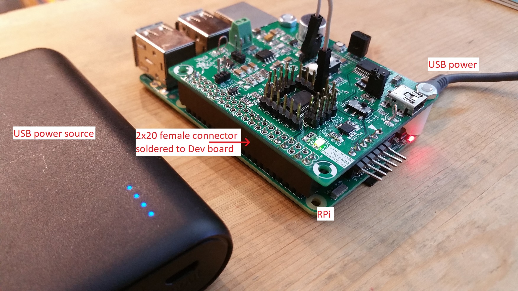
Please note that I did not solder all the header pins in place on the development board. You should solder all the pins to make a more secure mechanical connection. You can program the development board while connected to the RPi using the regular 6-pin header on the development board and the PIC Kit 3.
Finally, note that the RPi is being run in a headless configuration, meaning that there is no CRT, keyboard or mouse connected to the RPi. In the short run this is a pain because you will have to do all your RPi configuration through a terminal interface. However in the long-run this configuration allows you to embedded the RPi in many more application. Hauling around a monitor, keyboard and mouse makes the RPi unusable in most embedded applications. Trust me, this trade-off is worth it.
RPi configuration
There is a lot of good information about how to get a RPi up and running posted on the web. However, I would suggest following my RPi configuration instruction because they include instructions to:- Connect to the Mines wireless network,
- Get the NGINX web server up and running,
- Get the serial port up and running,
Web Interface to Dev board
You will need to populate the /var/www/html directory with the following files:- mic.py
- mic.php
- tx.py
- tx.php
- index.html
linux% sudo nano /var/www/html/mic.pyOnce you have the nano editor open, cut-and-paste the following contents into the file.
#!/usr/bin/python
import serial
serialport = serial.Serial("/dev/ttyS0", 9600, timeout =0.5)
serialport.write("m")
response = serialport.readlines(None)
print response
Finally save and exit.
linux% sudo nano /var/www/html/mic.phpOnce you have the nano editor open, cut-and-paste the following contents into the file.
<?php
$output = shell_exec('python mic.py');
$pos = strrpos($output,'[');
$len = strlen($output);
$rest = substr($output,$pos+2,3);
echo "<pre>$rest</pre>";
?>
Finally save and exit.
linux% sudo nano /var/www/html/tx.pyOnce you have the nano editor open, cut-and-paste the following contents into the file.
#!/usr/bin/python
import serial
serialport = serial.Serial("/dev/ttyS0", 9600, timeout =0.5)
serialport.write("l")
response = serialport.readlines(None)
print response
Finally save and exit. Before you leave, take a look at the code to see
what is going on. First the Python script creates a serial connection to
the /dev/ttyS0 port at 9600 baud. NExt it writes an "l" to the serial port.
This command will be interpreted by the development board as an order to
toggle the illumination level of the LED. Finally the python script expects
no response from the serial port and exits after printing the NULL
response.
linux% sudo nano /var/www/html/tx.phpOnce you have the nano editor open, cut-and-paste the following contents into the file.
<?php
shell_exec('python tx.py');
?>
Finally save and exit.
linux% sudo nano /var/www/html/index.htmlPaste the contents of the index.html file into the RPi (right-mouse click in PuTTY).
Troubleshooting
- Try connecting to the Dev'18 board through minterm.py. You should get the
following menu when you type "?".
?: help menu
o: k
m: display microhone level
l: toggle LED
If you do not get this menu, try resetting the Dev'18 through the MCLR line. I found that pulling the MCLR line high with a jumper wire solved a lot of my problems. You might want to consider putting an Oscope on the pins silk-screened RX1 and TX1 and type characters on the terminal looking for activity on these lines. If you do not get activity on the TX1 and RX1 when typing characters into miniterm then you might have a problem with the permissions on ttyS0. - Try running the python programs that read and write the Dev'18 board.
pi@raspberrypi:~$ sudo python tx.py
[]
pi@raspberrypi:~$ suso python mic.py
['124 ']
If these do not run, its probablly an issue with permissions. Here is a peek at my /var/www/html director using a long listing.pi@raspberrypi:/var/www/html $ ls -l total 20 -rwxr-xr-x 1 root root 1779 Dec 19 03:17 index.html -rwxr-xr-x 1 root root 160 Dec 19 03:17 mic.php -rwxr-xr-x 1 root root 168 Dec 19 03:28 mic.py -rwxr-xr-x 1 root root 37 Dec 19 03:18 tx.php -rwxr-xr-x 1 root root 168 Dec 19 03:28 tx.py
You can change file permission using the chmod command as follows:pi@raspberrypi:/var/www/html $ sudo chmod 755 index.html
- Try running the python programs through the web interface which monitoring things in miniterm. To do this run the php script by typing in "192.168.0.105/mic.php" where 192.168.0.105 is the IP address of the RPi on your home network. If everything is working you should get some text on the browser and may see some traffic on minterm.