1
In order to test next weeks program, it will be very helpful to have
a known waveform stored in the SD Card. Let's do future you a favor
and take care of this now. Copy the following sine wave
over and over again in the SD Card. You need to copy the wave
"smoothly" across block boundaries. In other words, when your code runs
out of room in one block at sin[index], the first value stored in the
next block should be sin[index+1], NOT sin[0]. Continue storing sine
waves until the user presses any key. After a keypress, tell the user
how many blocks have been stored.
const uint8_t sin[SINE_WAVE_ARRAY_LENGTH] = {128, 159, 187, 213, 233, 248, 255, 255, 248, 233, 213, 187, 159, 128, 97, 69, 43, 23, 8, 1, 1, 8, 23, 43, 69, 97};
W
This will record the microphone values converted through the ADC into the
SD Card at the sampling rate (default to 100 us). When the user types
'W' in the terminal window, prompt with user with
Press any key to start recording audio and
press any key to stop recording..
This will allow the user to get all set-up without having to pay attention
to which key they press in order to start the audio recording.
Your program must use double buffering so that it can acquire new samples
while storing old samples. To do this you will use the TMR0 ISR to
collected converted values from the ADC and start a new conversion.
In addition, the TMR0
ISR is responsible for moving the sampled value into either the red
or blue buffer (both global variables because of their size), and set
flags true to indicate when either buffer is full. Main should be
monitoring these flags and writing the red or blue buffer to the SD
Card when either is full. While main is doing this, the ISR should be
storing microphone samples to the other buffer.
Consider trying
Husker Scope
to record predictable waveforms.
If you didn't get the previous lab working?
If you did not get the previous lab working, you can
still complete this lab by recording your audio in the
foreground instead of sampling them in myTMR0ISR interrupt.
Do this by:
- Replacing your record function with the following code
- Delete all the record code from your myTMR0ISR.
- Add TMR1 with a 1:1 prescaler, Make sure to set
TMR1H = 0x00 and TMR0L = 0x00 in the Register configuration
of TMR1 when you use MCC!!!
This code will record audio onto your SD card. Now you can focus on
writing the the myTMR0ISR to playback the stored recording.
Before main declare:
#define BLOCK_SIZE              512

typedef enum {
    BEING_EMPTIED, EMPTY
} myBufferState_t;

typedef struct {
    myBufferState_t state;
    uint8_t buffer[BLOCK_SIZE];
} sdCardBlock_t;

sdCardBlock_t redBuffer, blueBuffer, silence;
Then inside main use:
                    //--------------------------------------------
                    // R: Record microphone store on SD card
                    //--------------------------------------------
                case 'R':
                    printf("Press any key to start recording of audio\r\n");
                    while (EUSART1_DataReady == false);
                    (void) EUSART1_Read();

                    loopSDcardAddress = 0;
                    //Added TMR1 with 1:1 prescaler and no interrupts to
                    // create the needed delays.

                    uint16_t redIndex = 0;
                    uint16_t blueIndex = 0;
                    printf("Press any key to stop recording of audio\r\n");
                    TMR1_WriteTimer(0x0000);
                    while (EUSART1_DataReady == false) {

                        for (redIndex = 0; redIndex < BLOCK_SIZE; redIndex++) {
                            ADCON0bits.GO_NOT_DONE = 1;
                            TMR1_WriteTimer(0x10000 - sampleRate + TMR1_ReadTimer());
                            PIR1bits.TMR1IF = 0;
                            while (!TMR1_HasOverflowOccured());
                            redBuffer.buffer[redIndex] = ADRESH;
                        }

                        SDCARD_WriteBlock(loopSDcardAddress, redBuffer.buffer);
                        while ((status = SDCARD_PollWriteComplete()) == WRITE_NOT_COMPLETE);
                        loopSDcardAddress += BLOCK_SIZE;

                        for (blueIndex = 0; blueIndex < BLOCK_SIZE; blueIndex++) {
                            TMR1_WriteTimer(0x10000 - sampleRate + TMR1_ReadTimer());
                            PIR1bits.TMR1IF = 0;
                            while (!TMR1_HasOverflowOccured());
                            blueBuffer.buffer[blueIndex] = ADRESH;
                        }

                        SDCARD_WriteBlock(loopSDcardAddress, blueBuffer.buffer);
                        while ((status = SDCARD_PollWriteComplete()) == WRITE_NOT_COMPLETE);
                        loopSDcardAddress += BLOCK_SIZE;
                    }
                    (void) EUSART1_Read();
                    playLengthInBlocks = loopSDcardAddress >> LOG_BLOCK_SIZE;
                    printf("Just wrote %d blocks to SD card, each page filled with audio data.\r\n", playLengthInBlocks);
                    break;
Volume hack
When you get the playback and record system to function correctly,
you will no doubt notice that the playback volume is very low. This
is due in part to the low corner frequency of the output low pass
filter and the low gain of the output amplifier. I provided you
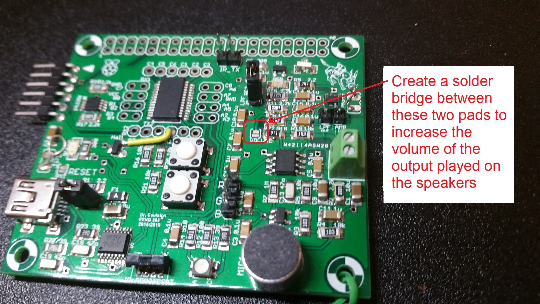
a means to increase the volume of the output by connecting the two
pads on the solder jumper labeled "volume" shown in the image below.
To do this, grab a piece of solder, heat up a solder iron and add solder
to the two pads until you intentionally create a solder bridge between
the two pads.

Note, that the down-side to this modification is that it will also
increase the volume level of the already loud square-wave output.
This may cause the development board to brown-out.
Turn-in
You may work with a single partner (or alone) to complete this lab.
Submit your main.c file on Canvas using the instructions posted
there. You should take note of the Rubric that will be used to evaluate
your assignment. Please form a group before submitting using the
instructions posted on Canvas. You will demonstrate your code at the
beginning of lab.
