EENG 393
Lab 7 - uSupply Footprints| Lab: | 7 |
| Status | Live |
InLab 7
Some self-guided activities.Lab 7 assignment
Add the following parts to your library and replace the equivlent part in your schematic with these parts.| Part | Foot | DigiKey part number | Source |
| LT3080 | TO-220-5R or SOT-223 | 505-LT3080IT#PBF-ND | Built from inLab instructions |
| LP2983 | SOT23-5 | LP2983AIM5-1.0/NOPBCT-ND | Downlod the footprint from SnapEDA |
| LP2985 | SOT23-5 | 296-24263-1-ND | Downlod the footprint from SnapEDA |
| Terminal Block | Custom | 277-6722-ND | Build from inLab instructions or find it on SNAP-EDA |
| Search | Library | Folder | Name | Description | |
| Search | Library | Folder | Name | Description | Value |
| *test* | testpad | TP | TPPAD-13(TP) | P1-13 | various names |
| *jump* | jumper | JP1E | JUMPER | GND, VOUT | |
| *c1206* | rlc | C-US | C-US1206 | C1206 | 10n, 2.2u |
| *DPDT* | SparkFun-Switches | SWITCH-DPDT | SWITCH_DPDT_SMD_AYZ0202 | SWITCH_DPDT_SMD_AYZ0202 |
Lab 6 schematic
After finishing lab 6, your schematic should similar to the following. After creating the footprints in the table above, you should replace the circuit elements circled in red. Also make sure to place the pair of linear regulators (the LP2985 and LP2983) and their associated bypass capcitors. Note that these capacitors are 1206 form factor, not Panasonic_B used previously.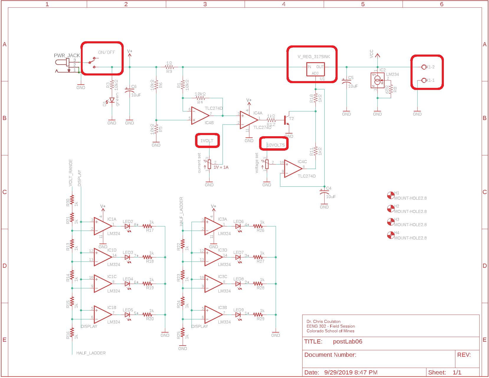
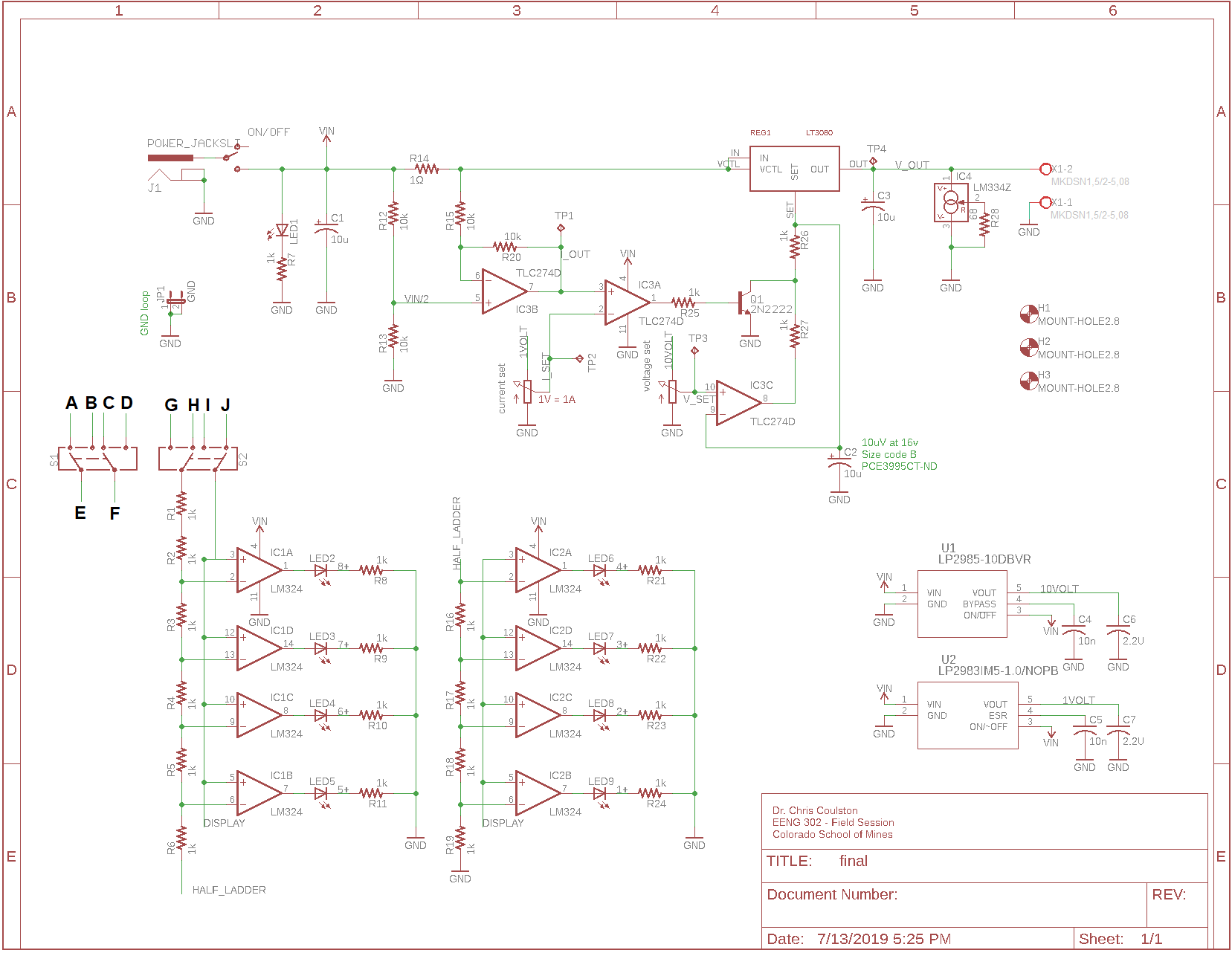
Lab 7 schematic
After replacing the components above and adding the additional parts called for, your schematic should look like the image below. You will need this completed schematic as the starting point for your lab next week.You will notice that the signals into the pair of DPDT switches are not properly designated. The last thing that you need to your schematic is to figure out how to get the VU meter to operate in ont of the following modes:
- Display V_SET
- Display I_SET
- Display V_OUT
- Display I_OUT
Complete the circuit in your schematic by placing the existing net names on A-J.
Turn-in
This is an individual assignment.Print the footprints for the LT3080, ON/OFF switch and the terminal block as PDF files using a scale factor of 5. Print the revised schematic of your uSupply as a PDF so that it fits on one page (scale factor about 0.9 should work) with the new parts and those asked for in the assignment.
Combine these PDFs into one file - you can use the combine your PDF files using https://combinepdf.com/ (Links to an external site.)in the following order:
- Page 1 - Revised schematic
- Page 2 - LT3080
- Page 3 - ON/OFF Switch