| Lecture: | 3 |
| Code |
|
| Class Objectives | Combinational Basic Building Blocks, Component instantiation, Generics |
Basic Building Blocks
While digital design has AND/OR/NOT gates at its foundation, in practice, we rarely use individual gates to design practical systems. Rather you will use pre-configured units of gates as the building blocks for your designs. Hence, we will call these pre-configured units, basic building blocks. All our basic building blocks will have the general structured shown below.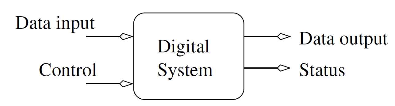
The relationship between the signals in a basic building block is given as follows:
In order to better understand how we might use these building blocks, it's worthwhile to look closely at one of the building blocks the generic 2:1 multiplexer.
Generic 2:1 Multiplexer
A multiplexer is a data routing device which sends one of the two inputs to the output depending on the value of the 1-bit select signal. The following table provides the specific names and widths of the signal used in our multiplexer.| Data input | 2 N-bit vectors y1 and y0 |
| Data output | N-bit vector f |
| Control input | 1-bit select |
| Status output | None |
| Behavior | f = y1 when select = 1, else f = y0 |
Look closely at the VHDL definition of the entity and architecture of the generic 2:1 multiplexer.
entity genericMux2x1 is
    generic(N: integer := 4);
    port(y1,y0:	 in std_logic_vector(N-1 downto 0);
	 select: in std_logic;
	 f:      out std_logic_vector(N-1 downto 0) );
end genericMux2x1;

architecture behavior of genericMux2x1 is
begin
    f <= y1 when s='1' else y0;
end behavior;
The entity contains the declaration generic(N: integer := 4). Let's
unpack this statement.
- generic means that there is a parameter that will be used in the entity and architecture.
- N is the name of this parameter. You may now use "N" in the entity and architecture definitions. Where ever you use "N" it will be replace by the value you give it when you use a genericMux2x1
- integer means that the only valid values for the parameter N are integers.
- :=4 means that if you do not provide a value for the parameter N, it will have a default value of 4.
Let's turn to the elephant in the room, how do you "use" the genericMux2x1? Great question!
Component Instantiation
I've been gritting my teeth while I wrote the previous paragraphs because every time that I used the expression "use a multiplexer" what I really wanted to say was "instantiate a multiplexer". I refrained because I wanted to fully cover the concept of generics before diving into instantation.When you instantiate a component in VHDL, you create a physical copy of the component that is placed on the FPGA that operates concurrent with all the other hardware in your design. You can make multiple instances of the same component, each is a unique, individual, and separate from the other instances.
The ability to instantiate components leads naturally to the idea of hierarchical design - the ability to include a component inside components inside components, etc... This ability to nest components allows us to hide unnecessary details inside a component and only show the "high level" behavior externally. In other words, hierarchical design allows you to abstract away the details of a design.
So let's try instantiating some components.
Min/Max Circuit
Let's flex our ability to describe digital designs using the basic building blocks template.| Data input | 2 N-bit vectors x and y |
| Data output | 2 N-bit vectors min and max |
| Control input | None |
| Status output | None |
| Behavior | min equals the smaller of x and y. max equals the larger of x and y |
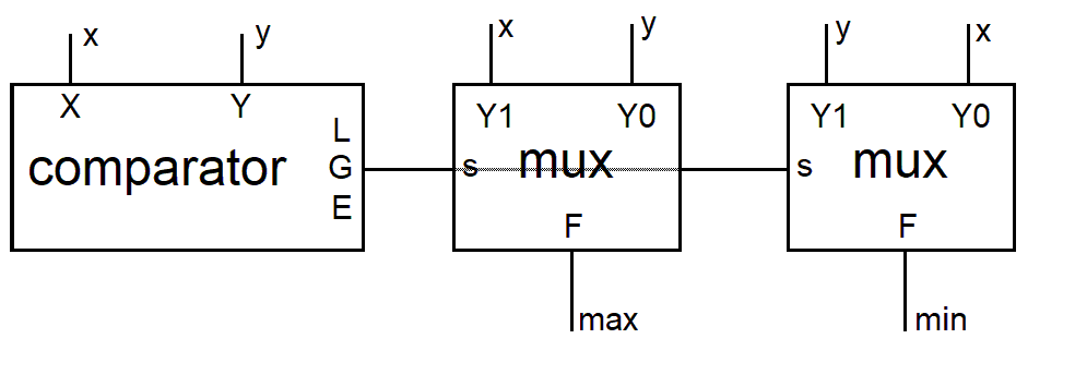
The role of the comparator in this design is to assert a logic 1 on its greater than output, G, when the x input is greater than y. When G equals 1, the left 2:1 mux will output x onto the max output and the right 2:1 mux will output y on the min output. I hope that this is a straight forward analysis.
Let's look at the VHDL code for the minMax circuit that will instantiate a comparator and two multiplexers.
---------------------------------------------------------------------------------- -- Comments start with two dashes -- You should always have the following -- lines in all of your code ---------------------------------------------------------------------------------- -- Name: Prof Chris Coulston -- Date: Fall 2022 -- Course: EENG 498 -- File: mod10Counter -- Purp: Classic mod 10 counter from EENg 294 Lab #8 -- -- Doc:Let's look at close look at the first multiplex instantation, the one that starts with max_mux.--
-- -- Academic Integrity Statement: I certify that, while others may have -- assisted me in brain storming, debugging and validating this program, -- the program itself is my own work. I understand that submitting code -- which is the work of other individuals is a violation of the honor -- code. I also understand that if I knowingly give my original work to -- another individual is also a violation of the honor code. ---------------------------------------------------------------------------------- library IEEE; use IEEE.STD_LOGIC_1164.ALL; use work.basicBuildingBlocks_package.ALL; entity minMax is port ( x, y : in STD_LOGIC_VECTOR(7 downto 0); min, max : out STD_LOGIC_VECTOR (7 downto 0)); end minMax; architecture structure of minMax is signal xGreaterY : STD_LOGIC; begin comp_inst : genericCompare GENERIC MAP(8) PORT MAP(x => x, y => y, g => xGreaterY, l => open, e => open); max_mux: genericMux2x1 GENERIC MAP(8) PORT MAP(y1 => x, y0 => y, s => xGreaterY, f => max); min_mux: genericMux2x1 GENERIC MAP(8) PORT MAP(y1 => y, y0 => x, s => xGreaterY, f => min); end structure;
- max_mux is the name of the instance. You should give each instance a unique name that will help you locate the instance when you are running your simulations - more on this later.
- genericMux2x1 is the name of entity/architecture that is being instantiated.
- GENERIC MAP(8) assigns the generic parameter N the value of 8. We know from previous discussion that this is the width of the input and output vectors. So all inputs and outputs to/from the multiplexer will be 8-bit signals. Checking the minMax entity, you can verify that x, y, max and min are 8-bit signals.
- PORT MAP tells the compiler that you are going to be assigning the signal in the genericMux2x1 entity values.
- y1 => x assigns the signal y1, that is in the genericMux2x1 entity, the calue of x, a signal that exists in the minMax architecture. We go on to assign every signal in the genericMux2x1 entity a value from signals whose scope is inside the minMax architecture.
- open The comparator has two unused signals, L and E. We assign these unused outputs the special value "open" to denote that these outputs are no connected to anything, they are open-circuit. Only outputs can have the value of open. NEVER give an input the value of open.
- use work.basicBuildingBlocks_package.ALL; is a library file that I created. It contains prototype for all the basic building blocks.
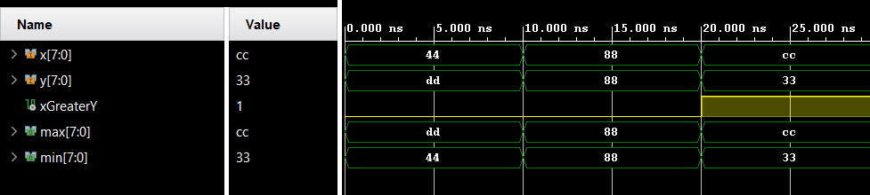
Verification
How should we go about showing that the VHDL code given above actually performs the correct min and max operations? Well, we will need a testbench, a topic that we will dive into during our next lecture. In preparation for that lecture, I created a testbench for he minMax circuit and generated the following timing diagram. Look it over and see if our design correctly performs the min max function.