| Lecture | 2 |
| Code | majority.vhdl |
| Class Objectives | TT to VHDL, STD_LOGIC_VECTOR, Literals, when/else statement |
VHDL
Your personality can be expressed through the code that you write. In lecture 1 we examined a structural method of describing a circuit; we transformed the circuit diagram into a textual description. Today we will examine another method of VHDL coding; behavioral.Behavioral
A behavioral description of a component describes what the circuit does rather than how it is done. One way to do this is to encode the truth table for a circuit directly into VHDL code. You can do this by assigning the output signal a value using the when/else structure. The idea is that you assign the output signal a value when the input signals have a specific value. Since the input signals can be arranged in variety of ways, you may need to use the else clause to specify a different output value associated with a different input signal.Let's look at a familiar example to see how this works, the 3-input majority circuit from lecture 1. Remember that this circuit outputs 1 when a majority of the three inputs are 1. In other words, when 2 or 3 of the inputs bits are 1, the output equals 1, else the output equals 0. The truth table for this circuit if given below.
a b c | f
------|--
0 0 0 | 0
0 0 1 | 0
0 1 0 | 0
0 1 1 | 1
1 0 0 | 0
1 0 1 | 1
1 1 0 | 1
1 1 1 | 1
The code snippet below uses this truth table to assign the output f a value using the multi-line when/else statement. I purposely structured this statement in the same row-order as the truth table. The first line of the when/else statement corresponds to the input a,b,c = 0,0,0. The last line of the when/else statement corresponds to the input a,b,c =1,1,1 because it was the only input combination not enumerated in the preceding 7-lines. The last line of a when/else should never be accompanied with a when statement . The reasons is because std_logic contains values beyond just 0 and 1 and as a consequence the last line of the when/else catches all these combinations of bit values not covered in the preceding when clauses. Notice that we need to put single quotes around the values of '0' and '1'. We'll come back to this.
------------------------------------------
-- Author:      Chris Coulston
-- Date:        Fall 2023
-- Purp:	Behavior Majority circuit
------------------------------------------
library IEEE;
use IEEE.std_logic_1164.all;

entity majority is
        port(	a, b, c	: in std_logic;
		f	: out std_logic);
end majority;

architecture behavior of majority is

begin

	f <=	'0' when a='0' and b='0' and c='0' else
		'0' when a='0' and b='0' and c='1' else
		'0' when a='0' and b='1' and c='0' else
		'1' when a='0' and b='1' and c='1' else
		'0' when a='1' and b='0' and c='0' else
		'1' when a='1' and b='0' and c='1' else
		'1' when a='1' and b='1' and c='0' else
		'1';

end behavior;
The when/else statement in the architecture acts as a
single concurrent signal assignment statements. Thus,
this CSA acts in parallel with any other statements that might
be in the architecture.Now let's return to the discussion surrounding the single quotes around literals.
Literals
A literal are fixed values that cannot be modified. Things like number or ASCII strings are common examples that you may have seen in previous courses. In VHDL single bits are surrounded with single quotes symbol ' and groups of bits are surrounded with the double quotes symbol ". You can specify a radix for a group of bits in front.'0' -- constant represents a single logic 0 bit "1010" -- constant represents four bits, default radix is binary x"a" -- constant represents for bits in hexadecimal
Vectors
So far, we have been dealing with individual bits with the datatype std_logic. While we could build almost any digital system with this datatype it would be laborious when we deal with multi-bit signals like the input and output from an adder circuit. So the creators of VHDL provide use with a datatype called std_logic_vector that allows us to manipulate a collection of signals using a single name, much like an array in a procedural programming language. When you want to use std_logic_vector you will need to- define the signal using a type declaration
- make a sub-vector of a signal using the downto operator
- concatenate vector using the & operator.
architecture silly of vectorExample is

	signal a3: std_logic_vector(2 downto 0);
	signal b4: std_logic_vector(3 downto 0);
	signal c5: std_logic_vector(4 downto 0);
	signal x: std_logic;

begin

	a3 <= "101";
	x <= a3[2] and '1';
	b4 <= a3 & '1';
	c5 <= b4[3 downto 2] & a3[1 downto 0];

end silly;
The bits of a std_logic_vector are given indicies specified by the bounds specified in parenthesis. We will always specify the largest bit index first followed by downto and then the index 0. Thus, the std_logic_vector a3 is 3-bits wide with its bits indexed as 2, 1 and 0. Likewise b4 is 4-bits wide and c5 is 5-bits wide.
You can grab individual or groups of bits from a vector using the the square bracket operator and listing the bit index or subvector range inside. If you select an individual bit from a vector, then you can use this signal just like any std_logic signal, like as the input to an AND gate.
You can combine bits using the concatenation operator &. When you concatenate two signals, the signal on the left becomes the most significant bits of the result and the right signal forms the least significant bits of the result.
So what are the resulting values of the signals is the above code snippet? Try it by yourself first, then look at the HTML source code for the comment just below for the answers.
Majority Circuit
Let's re-imagine the architecture of the majority circuit from earlier using vectors. Let's take advantage of the concatenation operator to make a vector out of the inputs a,b,c. We can do this by creating a signal in the architecture and assigning it the concatenation of a,b and c. The when/else then uses this vector to streamline the code and make it more readable.architecture behavior of majority is signal temp: std_logic_vector(2 downto 0); begin temp <= a & b & c; f <= '0' when temp = "000" else '0' when temp = "001" else '0' when temp = "010" else '1' when temp = "011" else '0' when temp = "100" else '1' when temp = "101" else '1' when temp = "110" else '1'; end behavior;
Don't cares in when/else statements
You can use don't cares in the when portion of a when/else statement to simply the logic and number of lines in the statement. If a bit of the input can equal 0 or 1 with no change in the output, you can replace that bit value with a don't care. The symbol for a don't care is the dash, -.As an exercise, determine the truth table for the following when/else statement. The solutions are viewable in the page source as a comment.
	temp <= a & b & c;
	f <=	'1' when temp = "10-" else
		'1' when temp = "-10" else
		'0' when temp = "0-1" else
		'0' when temp = "00-" else
		'1';
Hex to Seven Segment converter
The hexadecimal-to-seven-segment-decoder is a combinational circuit that converts a 4-bit hexadecimal number to an appropriate code that drives a 7-segment display the corresponding value. Let's assume that the LEDs in our 7-segment display are active low, meaning that they illuminate when you send them a logic 0. The following shows the bit index for the individual segments of the 7-segment display. So in order to produce an illuminated pattern that looks like the number 4 we would have to send the 7-segment display the vector "0011001"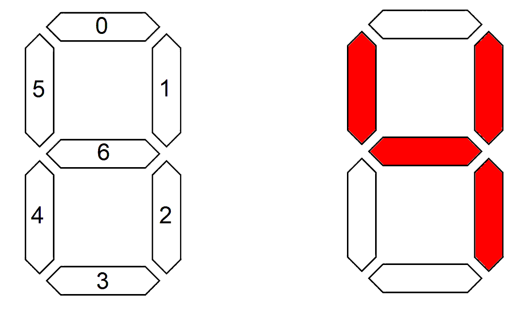
Now let's turn to writing the VHDL code for the hex2Seven component. Let's start with entity and describe the inputs and outputs. The input is 4-bits so we should make it a std_logic_vector(3 downto 0). I'd give the input a name like "hex" and the output "sevenSeg".
We will use an when/else statement to describe the behavior of the hex2Seven component. All we really need to know is the bit patterns needed to correctly illuminate the LEDs for each hex input. To help with this, I've included the expected output for each hex input.
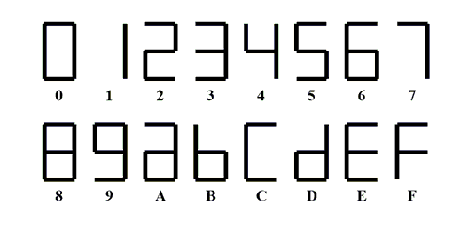
If you still have your EENG 284 labs lying around, you will be able to look at the Verilog code for lab #2 to get the bit patterns for each input. I'd like you to try to write the code yourself using the provided code in this lecture note as a template. When you are complete, look at the source code for this web page to find the solution in the comments.