| Lecture | 10 |
| Class Objectives | Understand how the waveforms produced by a VGA output generate the image shown on the screen. |
Lab 02
For lab #2 you will use the Vivado tools to write the VHDL code for an vgaToHdmiConverter component. We will use this component later to display data captured by a high speed ADC.VGA signals
The video graphics adapter (VGA) standard displays images by sweeping a beam across the computer screen from left to right in a row. When the beam reaches the right side of the screen relies on 5 signals to draw images on a VGA compatiable display:- red - a 8-bit value that sets the intensity of red at the current pixel location. The larger the value, the more intense the red produced.
- green - a 8-bit value that sets the intensity of green at the current pixel location. The larger the value, the more intense the green produced.
- blue - a 8-bit value that sets the intensity of blue at the current pixel location. The larger the value, the more intense the blue produced.
- horziontal synch - When the pi
- vertical synch
HD Video Overview
The HD Video standard is an interface protocol used to transmit video data to a screen. The HD Video protocol uses a scanning method to project an image on the screen. Starting in the top-left of the screen, the monitor will progressively move from left to right, top to bottom to display each pixel. The following signals must be sent to a HDMI equiped monitor in order to display an image.red,green,blue- three separate 8-bit signals indicating the amount of each color to display in the current pixel. These signals are sometimes abbreviated as RGB.h_sync- Horizontal synchronization signal that tells the screen to start writing pixels to the next linev_sync- Vertical synchronization signal that tells the screen that the current video frame is completed. After receiving a vertical synch signal, the screen then starts writing pixels to the top-left of the screen.
front_porch, sync_pulse,
back_porch, and active_video. Incoming pixel
data (through the RGB channels) is only displayed during the active_video
state of the synchronization signals.The h_cnt value will count up from 0 to 1650 at 74.25MHz. The
pixel_clk
carries this clock signal and is generated using the video_clk module. You should
use the h_cnt counter's value to generate the h_synch and h_active signals using
simple range comparisions. You can generate the pixelHorz value as h_cnt minus
the width of the front_porch + synch + back_porch in the active video area.
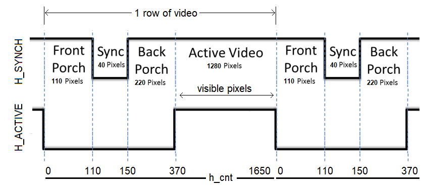
Figure 1: The
h_sync signal contains four
states. Pixel data is only displayed on the monitor during the
active_video state. During all other state, the RGB values must be
"0".The v_cnt value will count up from 0 to 750. The v_cnt value is incremented every time a row of video is drawn. So v_cnt counts up much more slowly than h_cnt. You should use the v_cnt counter's value to generate the v_synch and v_active signals using simple range comparisions. You can generate the pixelVert value as v_cnt minus the width of the front_porch + synch + back_porch in the active video area.
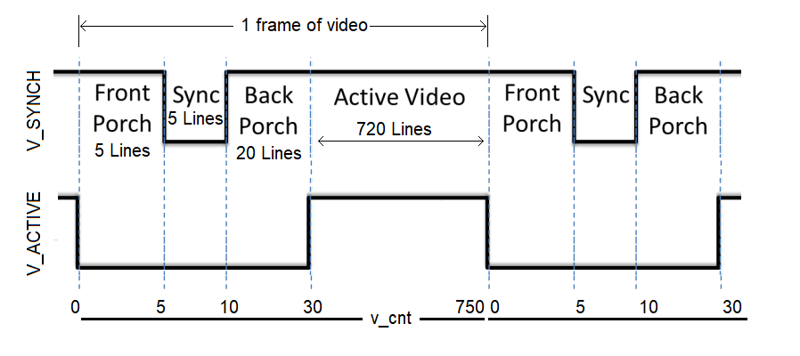
Figure 2: The
v_sync signal is similar
to h_sync, but instead of counting based on
pixel_clk, the states are based on the number of iterations
of the h_sync signal. Pixel data is only displayed on the
monitor during the active_video state. During all other state, the RGB
values must be "0".