| Lecture | 1 |
| Code | majority.vhdl |
| Class Objectives | Symbolic and Circuit to VHDL, Entity/Architecture, STD_LOGIC, CSA |
GOAL
There are several goals for this course.- You will learn to practice digital design. You should know how to design complex digital systems. In this class you will learn how to implement such circuits.
- You will gain hands-on experience using a variety of common devices. These devices are used by digital designers and many have been used in your senior design projects.
- You will be exposed to some advanced techniques used in digital design. If you pursue an advanced degree these are the topics that you may encounter.
- Prepare you for your capstone design project by allowing you to develop a project idea, plan, and implementation.
VHDL
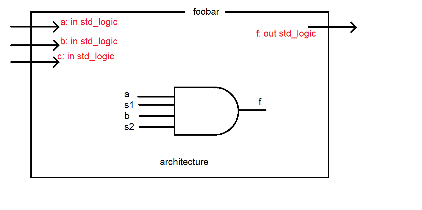
VHDL is a language which is used to describe hardware circuits. You will find that its a logically organized language that naturally utilizes the concept of hierarchical design; breaking a complex system into components which themselves are composed of components. A piece of hardware is described in VHDL in two separate ways.- The ENTITY describes the name of the component and the name and type of the inputs and outputs. In the image below, the entity is named foobar and there are 3 bits of input a,b,c. The datatype "std_logic" is synonymous with a bit. There is a single bit of output f. A component can have more than one bit of output.
- The ARCHITECTURE describes what transformation the box performs. In other words the behavior of the component. In the image below there is a big AND gate which represents the logic inside this component. The input signal a and b are used as inputs to this AND gate along with two signals s1 and s2. These two bits must have been created somewhere else in the architecture and were not shown. You can think of s1 and s2 as local variables. One important note, you CANNOT use an output of the entity (f in our case), as an input to a gate inside the architecture. If you would want to do that, you would have to make a copy of f as a "local variable" and use it as an input.2
There are two good reasons to realize a design in VHDL, you can simulate and synthesize hardware specified.
Simulation
When a design is simulated you have complete control of time and the values of all the signals (wires) in the design. This greatly aides debugging because the entire design is transparent. We will use a program called ModelSim to perform our VHDL simulations.Synthesis
Synthesis means make the VHDL description "real". Real in the sense that a logical circuit will have the same I/O and behavior as the VHDL description. Synthesis implies that there is a target piece of hardware to accept the synthesized VHDL description. In our class we will use the Xilinx Zunq 7010 chip as our target. This chip contains components (CLBs) which can be reconfigured using a special file called a bit file. The Vivado software performs the translation between VHDL and the Zynq chip.Now that we have some motivation of what we are doing and why, lets proceed to write some VHDL code. Rather than go though a long list of the commands in VHDL (and there are a lot of them), I think that its easier to look at a simple example.
Majority circuit
Digital design is the process of taking an abstract idea for a digital system and translating it into an actuality. In order to make the process more manageable, we successively refine the design in steps, with each step being a little bit more real than the previous. Simple digital systems typically have a nice clean design process as exemplified by the following problem. Word Statement Build a circuit (SOP min) with 3-bits of input and 1-bit of output. The output equals 1 when a majority of the three inputs equal 1.Truth Table
a b c | f
------|--
0 0 0 | 0
0 0 1 | 0
0 1 0 | 0
0 1 1 | 1
1 0 0 | 0
1 0 1 | 1
1 1 0 | 1
1 1 1 | 1
Kmap You know what to do..
Circuit Diagram This will be very important in your VHDL because essentially you will write a text description of this circuit. Notice in the diagram below that every wire which begins and ends inside the box is given its own label. These wires (labeled s1,s2,s3) are like local variables in a regular programming language. The inputs (a,b,c) and the output (f) are like the values that are passed into and out of a function in a programming language.
VHDL
In class we will examine which of the lines below are reserved words and which are created by us.
--------------------------------------------------------------------
-- Name:<Your Name>
-- Date:<The date you stated working on the file>
-- File:<This file's name>
-- HW:	<HW# and name>
--
-- Purp:A brief description of what this program does and
--	the general solution strategy.
--
-- Doc:	<list the names of the people who you helped>
-- 	<list the names of the people who assisted you>
--
-- Academic Integrity Statement: I certify that, while others may have
-- assisted me in brain storming, debugging and validating this program,
-- the program itself is my own work. I understand that submitting code
-- which is the work of other individuals is a violation of the honor
-- code.  I also understand that if I knowingly give my original work to
-- another individual is also a violation of the honor code.
-------------------------------------------------------------------------
library IEEE;			-- This line is EXACTLY like #include in C
use IEEE.std_logic_1164.all;

entity majority is
        port(	a, b, c:	in std_logic;
		f:   		out std_logic);
end majority;

architecture structure of majority is
signal	s1, s2, s3: std_logic;	-- wires which begin and end in the component

begin
	s1 <= a and c;		-- These statements are called
	s2 <= c and c;		-- concurrent signal assignments.
	s3 <= a and b;		-- They all happen at the same time
	f <= s1 or s2 or s3;	-- unlike a regular programming lang.
end structure;
The real "meat and potatoes" of the VHDL description are the four lines in the architecture:
        s1 <= a and c;
        s2 <= c and c;
        s3 <= a and b;
        f <= s1 or s2 or s3;
What separates VHDL from a normal programming language is that these
four lines are executed continuously in parallel. This implies that
the order of the lines is completely irrelevant, any order of these
four lines would work as well as any other. In addition each of
these lines is always in execution. This should make sense from a
hardware perspective; each of the gates in the majority circuit
is continuously examining its inputs and asserting an appropriate
output.
Important Notes
You can use all the standard logic gates including:- AND
- OR
- XOR
- NAND
- NOR
- XNOR
- NOT